SFI SYSTEM
-
OPERATION
-
VVT-iE
-
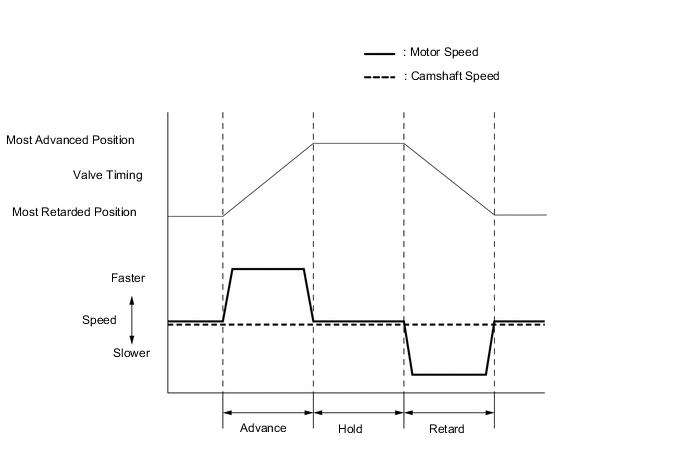
The ECM controls the advance and retard operation by way of the speed difference between the motor and the camshaft. The ECM maintains the valve timing by rotating the motor at the same speed as the camshaft.
-
To advance the camshaft timing, the motor speed becomes faster than the camshaft rotational speed.
-
To retard the camshaft timing, the motor speed becomes slower than the camshaft rotational speed. (Depending on the camshaft speed, the motor may rotate counterclockwise.)
-
-
As advance signals from the ECM cause the cam timing control motor with EDU assembly to rotate faster than the camshaft, the camshaft gear rotates in the direction shown in the illustration via the reduction unit. This rotation causes the intake camshaft coupled with the camshaft gear to rotate in the advance direction.
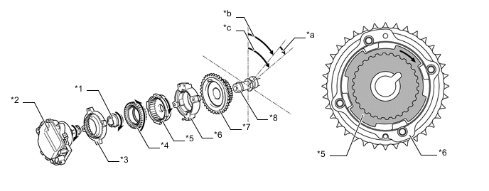
*1 Eccentric Shaft *2 Cam Timing Control Motor with EDU Assembly *3 Sprocket Gear *4 Planetary Gear *5 Camshaft Gear *6 Housing *7 Sprocket *8 Intake Camshaft *a Advance Side *b Sprocket Speed *c Camshaft Speed - - -
As retard signals from the ECM cause the motor to rotate slower than the camshaft, the camshaft gear rotates in the direction shown in the illustration via the reduction unit. This rotation causes the intake camshaft coupled with the camshaft gear to rotate in the retard direction. The motor turns clockwise and counterclockwise in accordance with engine conditions.
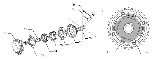
*1 Eccentric Shaft *2 Cam Timing Control Motor with EDU Assembly *3 Sprocket Gear *4 Planetary Gear *5 Camshaft Gear *6 Housing *7 Sprocket *8 Intake Camshaft *a Retard Side *b Sprocket Speed *c Camshaft Speed - - -
After the target valve timing has been reached, the ECM rotates the motor at the same speed as the camshaft. As a result, the VVT-iE becomes locked, thus holding the camshaft at the valve timing.
-
-
VVT-i
-
VVT-i consists of camshaft timing exhaust gear assemblies that operate by engine oil pressure and the cam timing oil control valve assemblies that switch the engine oil pressure passages in accordance with the signals from the ECM.
-
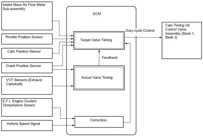
Based on the engine speed, intake air volume, throttle position, vehicle speed, and engine coolant temperature, the ECM calculates optimal valve timing for all driving conditions. The ECM uses the calculated valve timing as the target valve timing to control the cam timing oil control valve assemblies. In addition, the ECM uses signals from the VVT sensors (exhaust) and the crank position sensor to detect the actual valve timing, thus providing feedback control to achieve the target valve timing.
-
When the cam timing oil control valve assembly is positioned as illustrated below by a duty cycle provided by the ECM, the resultant oil pressure is applied to the timing advance side vane chamber to rotate the camshaft in the timing advance direction.
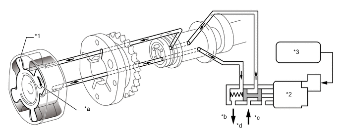
*1 Vane *2 Cam Timing Oil Control Valve Assembly *3 ECM - - *a Rotation Direction *b Drain *c In *d Oil Pressure -
When the cam timing oil control valve assembly is positioned as shown in the illustration below by a duty cycle provided by the ECM, oil pressure is applied to the timing retard side vane chamber to rotate the camshaft in the timing retard direction.
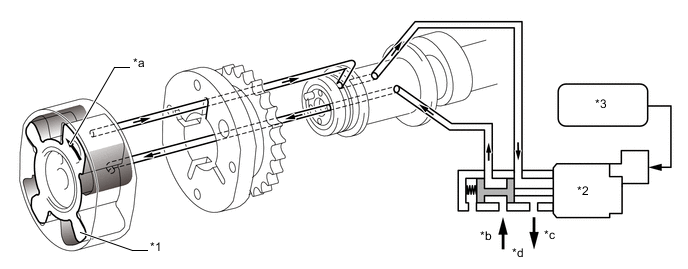
*1 Vane *2 Cam Timing Oil Control Valve Assembly *3 ECM - - *a Rotation Direction *b In *c Drain *d Oil Pressure -
After reaching the target timing, the engine valve timing is maintained by keeping the cam timing oil control valve assembly in the neutral position unless the engine operating conditions change. This maintains the valve timing at the desired target position by preventing the flow of engine oil to and from each chamber.
-
-