SFI SYSTEM
Figure 1. Destination Package for South Korea
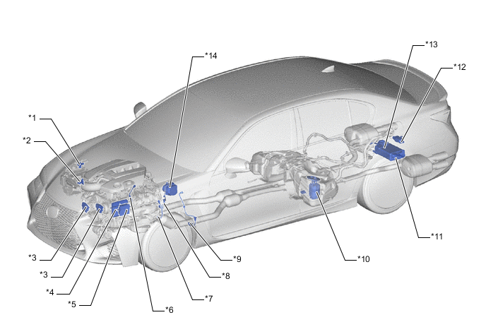
| *1 | VSV (for Air Intake Control Valve) | *2 | Intake Mass Air Flow Meter Sub-assembly
|
| *3 | Cooling Fan ECU | *4 | ECM |
| *5 | TCM | *6 | Air Fuel Ratio Sensor (Bank 2 Sensor 1) |
| *7 | Air Fuel Ratio Sensor (Bank 1 Sensor 1) | *8 | Oxygen Sensor (Bank 2 Sensor 2) |
| *9 | Oxygen Sensor (Bank 1 Sensor 2) | *10 | Fuel Pump (Low Pressure) |
| *11 | Canister | *12 | Fuel Pump Control ECU |
| *13 | Canister Pump Module
|
*14 | Brake Actuator Assembly
|
Figure 2. Except Destination Package for South Korea
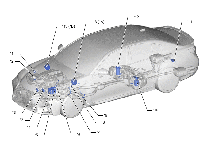
| *A | LHD Models | *B | RHD Models |
| *1 | VSV (for Air Intake Control Valve) | *2 | Intake Mass Air Flow Meter Sub-assembly
|
| *3 | Cooling Fan ECU | *4 | ECM |
| *5 | TCM | *6 | Air Fuel Ratio Sensor (Bank 2 Sensor 1) |
| *7 | Air Fuel Ratio Sensor (Bank 1 Sensor 1) | *8 | Oxygen Sensor (Bank 2 Sensor 2) |
| *9 | Oxygen Sensor (Bank 1 Sensor 2) | *10 | Fuel Pump (Low Pressure) |
| *11 | Fuel Pump Control ECU | *12 | Fuel Tank Vent Tube Assembly
|
| *13 | Brake Actuator Assembly
|
- | - |
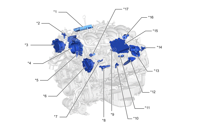
| *1 | No. 1 EDU (Injector Driver) | *2 | Cam Position Sensor |
| *3 | Cam Timing Control Motor with EDU Assembly RH | *4 | Throttle Body with Motor Assembly
|
| *5 | E.F.I. Engine Coolant Temperature Sensor | *6 | Cam Timing Control Motor with EDU Assembly LH |
| *7 | Knock Control Sensor (Bank 1 Sensor 1) | *8 | Cam Timing Oil Control Valve Assembly (LH) |
| *9 | Knock Control Sensor (Bank 2 Sensor 2) | *10 | VVT Sensor (Bank 1 Exhaust) |
| *11 | Knock Control Sensor (Bank 1 Sensor 2) | *12 | Ignition Coil Assembly |
| *13 | Fuel Pump Assembly (for High Pressure) (Bank 1) | *14 | VVT Sensor (Bank 1 Intake) |
| *15 | No. 2 EDU (Injector Driver) | *16 | Purge VSV |
| *17 | Knock Control Sensor (Bank 2 Sensor 1) | - | - |
| *1 | Fuel Pressure Sensor | *2 | Fuel Injector Assembly (for Port Injection) |
| *3 | VVT Sensor (Bank 2 Intake) | *4 | Fuel Injector Assembly (for Direct Injection) |
| *5 | Crank Position Sensor | *6 | Fuel Pump Assembly (for High Pressure) (Bank 2) |
| *7 | VVT Sensor (Bank 2 Exhaust) | *8 | Cam Timing Oil Control Valve Assembly (RH) |
Figure 3. LHD Models
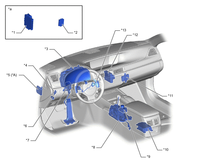
| *A | Models with Lexus Safety System + | - | - |
| *1 | Certification ECU (Smart Key ECU Assembly) | *2 | ID Code Box (Immobiliser Code ECU) |
| *3 | Combination Meter Assembly
|
*4 | Stop Light Switch Assembly |
| *5 | Driving Support ECU Assembly | *6 | DLC3 |
| *7 | Accelerator Pedal Sensor Assembly
|
*8 | Transmission Floor Shift Assembly
|
| *9 | Combination Switch Assembly
|
*10 | Airbag ECU Assembly |
| *11 | Network Gateway ECU | *12 | Air Conditioning Amplifier Assembly |
| *13 | Shift Paddle Switch (Transmission Shift Switch Assembly) | - | - |
| *a | Refer to Service Bulletin for the installation position of the part. | - | - |
Figure 4. RHD Models
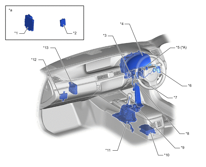
| *A | Models with Lexus Safety System + | - | - |
| *1 | Certification ECU (Smart Key ECU Assembly) | *2 | ID Code Box (Immobiliser Code ECU) |
| *3 | Stop Light Switch Assembly | *4 | Combination Meter Assembly
|
| *5 | Driving Support ECU Assembly | *6 | Shift Paddle Switch (Transmission Shift Switch Assembly) |
| *7 | DLC3 | *8 | Accelerator Pedal Sensor Assembly
|
| *9 | Combination Switch Assembly
|
*10 | Airbag ECU Assembly |
| *11 | Shift Paddle Switch (Transmission Shift Switch Assembly) | *12 | Network Gateway ECU |
| *13 | Air Conditioning Amplifier Assembly | - | - |
| *a | Refer to Service Bulletin for the installation position of the part. | - | - |