СИСТЕМА МЕХАНИЧЕСКОЙ ТРАНСМИССИИ
-
CONSTRUCTION
-
The No. 1 and No. 2 output shafts are placed on the circumference of the differential ring gear.
-
The reverse idler gear is engaged with the 1st and reverse drive gear of the input shaft and the reverse driven gear of the No. 2 output shaft.
-
The 1st, 2nd, 3rd and 4th driven gears are located on the No. 1 output shaft.
-
The 5th, 6th and reverse driven gears are located on the No. 2 output shaft.
-
Triple-cone type (for 1st gear to 3rd gear), double-cone type (for 4th gear) and single-cone type (for 5th, 6th and reverse gears) synchromesh mechanisms are used to reduce the shifting effort and obtain smoother shifting.
-
The reverse type synchromesh mechanism is used for the reverse gear to enhance the ease of operation.
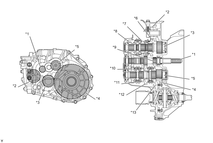
*1 Input Shaft *2 Reverse Idler Gear *3 No. 2 Output Shaft *4 Differential Ring Gear *5 No. 1 Output Shaft *6 Reverse Driven Gear *7 5th Driven Gear *8 6th Driven Gear *9 1st and Reverse Drive Gear *10 3rd Driven Gear *11 4th Driven Gear *12 2nd Driven Gear *13 1st Driven Gear - -
-