СИСТЕМА АВТОМАТИЧЕСКОЙ ТРАНСМИССИИ
-
FUNCTION OF MAIN COMPONENTS
Component Function ATF Warmer (Transmission Oil Cooler) Warms up the ATF quickly. Torque Converter Assembly
-
Transmits engine power to the transaxle.
-
Increases engine torque.
Oil Pump Assembly Provides oil pressure necessary for the transaxle operation. No. 1 Clutch (C1) Connects the intermediate shaft and the Ravigneaux planetary rear sun gear. No. 2 Clutch (C2) Connects the intermediate shaft and the Ravigneaux planetary ring gear. No. 1 Brake (B1) Prevents the Ravigneaux planetary front sun gear and the underdrive planetary carrier from turningclockwise or counterclockwise. No. 2 Brake (B2) Prevents the Ravigneaux planetary ring gear from turning clockwise or counterclockwise. No. 3 Brake (B3) Prevents the underdrive planetary ring gear from turning clockwise or counterclockwise. No. 1 1-way Clutch (F1) Prevents the Ravigneaux planetary ring gear from turning counterclockwise. Planetary Gears Change the route through which driving force is transmitted in accordance with the operation of each clutch and brake in order to increase or reduce the input and output speed. Shift Solenoid Valve SL1 Controls the No. 1 clutch (C1) pressure. Shift Solenoid Valve SL2 Controls the No. 2 clutch (C2) pressure. Shift Solenoid Valve SL3 Controls the No. 1 brake (B1) pressure. Shift Solenoid Valve SL4 Controls the No. 3 brake (B3) pressure. Shift Solenoid Valve SLU
-
Controls the lock-up clutch pressure.
-
Controls the No. 2 brake (B2) pressure.
Shift Solenoid Valve SLT Controls line pressure. Shift Solenoid Valve SL
-
Switches the lock-up relay valve.
-
Switches the B2 apply control valve and the reverse sequence valve.
Counter Gear Speed Sensor Detects the speed of the counter gear. Input Turbine Speed Sensor Detects the input speed of the transaxle. ATF Temperature Sensor Detects the ATF temperature. Park/Neutral Position Switch Assembly Detects the shift lever position. Transmission Control Switch
-
Detects that the shift lever is in S.
-
Detects the driver's upshift and downshift operations when the shift lever is in S.
Combination Switch Assembly Sport Mode Switch Turns the Sport mode on and off. ECO Mode Switch Turns the ECO mode on and off. ECM
-
Controls engine output and each shift solenoid valve in response to a signal from each sensor and switch.
-
Makes a diagnosis and memorizes the failed section when the ECM detects a malfunction.
Air Conditioning Amplifier Assembly
-
Transmits the operating state of the air conditioning system to the ECM.
-
Outputs the ECO mode signal to the ECM.
Driving Support ECU Assembly*1 Sends the information about the operation conditions of the dynamic radar cruise control system to the ECM. Combination Meter Assembly Sport Mode Indicator Light*2 Illuminates when Sport mode is active. ECO Mode Indicator Light*2 Illuminates when ECO mode is active. MIL Illuminates or blinks to inform the driver when the ECM detects a malfunction. Master Warning Light*3 Warns the driver by lighting up when a message is shown on the multi-information display. Multi-information Display
-
Displays the drive mode.*3
-
Displays the shift lever position.
-
Displays the shift range.
Buzzer
-
Sounds when the downshift operation is rejected.
-
Warns the driver by sounding when a message is shown on the multi-information display.*3
*1: Models with dynamic radar cruise control system
*2: Models with analog type combination meter assembly
*3: Models with Optitron type combination meter assembly
-
-
SYSTEM CONTROL
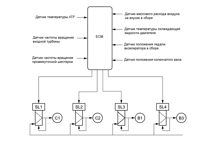
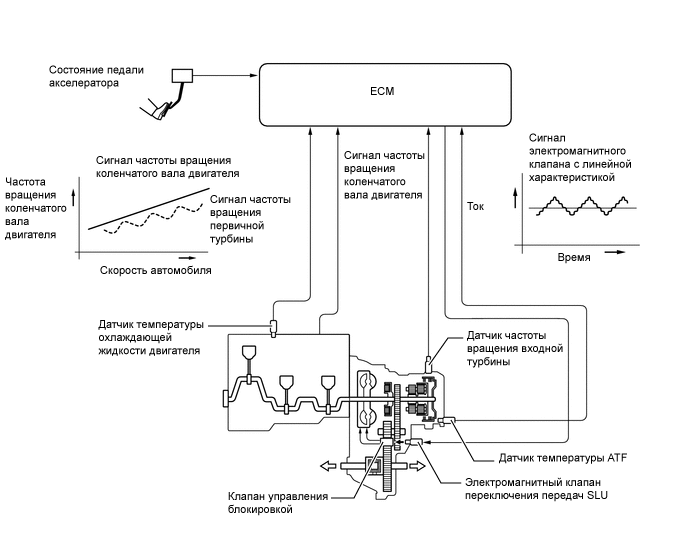
Electronic Control of Automatic Transaxle Control Outline Shift Timing Control The ECM sends current to shift solenoid valves SL1, SL2, SL3, SL4 and/or SLU based on signals from various sensors in order to shift the gears. Clutch to Clutch Pressure Control Controls the pressure applied directly to the No. 1 Clutch (C1), No. 2 Clutch (C2), No. 1 Brake (B1) and No. 3 Brake (B3) by actuating the shift solenoid valves (SL1, SL2, SL3 and SL4) in accordance with ECM signals. Line Pressure Optimal Control Actuates the shift solenoid valve SLT to control the line pressure in accordance with information from the ECM and the operating conditions of the transaxle. Powertrain Cooperative Control Performs both shift control and engine output control in an integrated way, achieving excellent shift characteristics and driveability. Artificial Intelligence-shift Control (AI-shift Control) Based on the signals from various sensors, the ECM determines the road conditions and the intention of the driver. Thus, an appropriate shift pattern is automatically determined, improving driveability. Deceleration Downshift Control To prevent engine speed from decreasing and thereby maintain the fuel cut, the ECM performs downshifts before the fuel cut ends. Direct Downshift Control Makes it possible to skip unnecessary shifts, enabling the vehicle to downshift directly from 6th to 3rd or from 5th to 2nd, enhancing downshift response when the accelerator pedal is depressed quickly. Lock-up Timing Control The ECM sends current to the shift solenoid valves SL and SLU based on signals from various sensors to engage or disengage the lock-up clutch. Flex Lock-up Clutch Control Controls the shift solenoid valve SLU, provides an intermediate mode between the on and off states of the lock-up clutch, and increases the operating range of the lock-up clutch to improve fuel economy. Multi-mode Automatic Transmission The ECM appropriately controls the automatic transaxle in accordance with the shift range selected using the shift lever while the shift lever is in S. High Response Upshift Control Achieves a crisp and high response upshift using the clutch to clutch pressure control and powertrain cooperative control. Blipping Downshift Control Achieves smooth and quick downshift using clutch to clutch pressure control and powertrain cooperative control.
-
Clutch to Clutch Pressure Control
-
Clutch to clutch pressure control is used for shift control. As a result, shift control in 2nd gear or above can be performed without using a 1-way clutch, making the automatic transaxle lightweight and compact.
-
Based on the information about transaxle input and output speed, engine torque and other items, the ECM controls each clutch and brake in accordance with the optimum fluid pressure and timing, in order to shift the gears. The ECM changes gears using fluid pressure circuits which enable the No. 1 clutch (C1), No. 2 clutch (C2), No. 1 brake (B1) and No. 3 brake (B3) to be controlled independently, and using the high flow SL1, SL2, SL3 and SL4 shift solenoid valves which directly control the line pressure. As a result, highly responsive and excellent shift characteristics have been achieved.
-
-
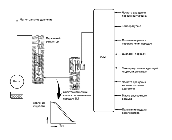
Line Pressure Optimal Control
-
The line pressure is controlled using shift solenoid valve SLT.
-
Through the use of shift solenoid valve SLT, the line pressure is optimally controlled in accordance with the engine torque information, as well as with the internal operating conditions of the torque converter and the transaxle.
-
Accordingly, the line pressure can be accurately controlled in accordance with the engine output, traveling condition and the ATF temperature, thus achieving smooth shift characteristics and regulating the workload of the oil pump (reducing unnecessary parasitic losses).
-
-
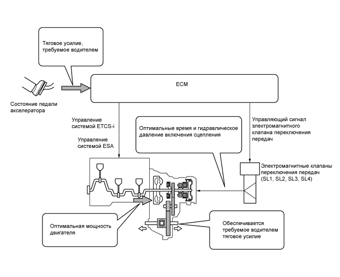
Powertrain Cooperative Control
-
Throttle Control at Starting
-
The engine output is optimally controlled using the Electronic Throttle Control System-intelligent (ETCS-i) in real time and in accordance with the transient force from the torque converter when the vehicle is launched. This achieves a suppressed sense of lurching forward, tire slippage suppression and improved responsiveness, ensuring excellent launch performance.
-
-
Deceleration Force Control
-
The ECM determines the gear that is to be selected when the accelerator pedal is released (released completely) in accordance with the way the accelerator pedal is released (suddenly or slowly) during deceleration. In this way, unnecessary upshifts are prevented during deceleration, matching the driver's intentions. In addition, unintended downshifts are prevented when accelerating the vehicle again, achieving smooth acceleration.
-
-
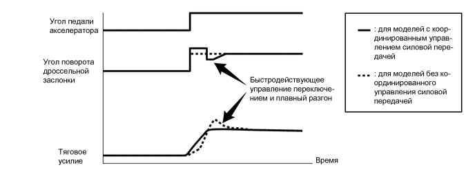
Transient Shifting Control
-
Through cooperative control with the Electronic Throttle Control System-intelligent (ETCS-i) and Electronic Spark Advance (ESA), and electronic control of the engagement and release speed of the clutch and brake hydraulic pressures, quick response and shift shock reduction have been achieved.
-
-
-
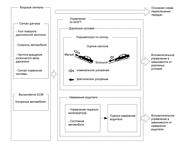
Artificial Intelligence Shift Control (AI-shift Control)
-
The automatic transaxle gear is determined by the shift pattern, which uses the vehicle speed and accelerator pedal depression angle.
-
Additionally, AI-shift control enables the ECM to estimate the road conditions and the driver's intention in order to automatically control the shift pattern in an optimal manner. As a result, a comfortable ride has been achieved.
-
AI-shift control includes road condition support control and driver's intention support control.
-
AI-shift control determines optimal transaxle control based on input signals and automatically changes the shift pattern.
-
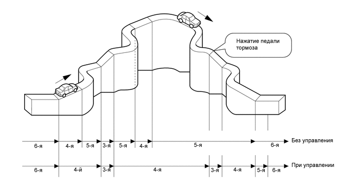
Road Condition Support Control
-
Under road condition support control, the ECM determines from the accelerator pedal depressing angle and the vehicle speed whether the vehicle is being driven uphill or downhill. To achieve the optimal drive force while driving uphill, this control prevents unnecessary upshifts. To achieve the optimal engine brake effect while driving downhill, this control automatically performs downshifts.
-
-
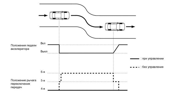
Driver's Intention Support Control
-
The driver's intention is estimated based on the accelerator pedal depression angle and vehicle condition to switch to a shift pattern that is well-suited to the driver.
-
-
Quick Brake Downshift Control
-
When sudden braking is applied in Sport mode, the quick brake downshift control improves re-acceleration response and engine brake force by downshifting.
-
-
-
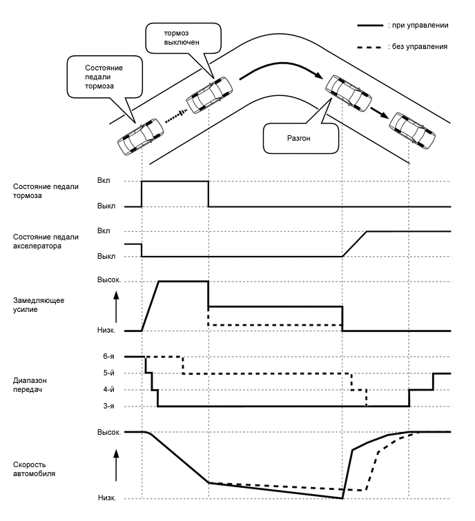
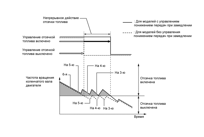
Deceleration Downshift Control
-
The ECM performs downshift control to help prevent the engine speed from decreasing, thus keeping fuel cut control operating for as long as possible. In this way, fuel economy is improved.
-
When the vehicle is in 6th gear and starts decelerating, the transaxle downshifts from 6th to 5th, 5th to 4th and 4th to 3rd* before fuel cut control ends so that the fuel cut control can continue operating.
Tech Tips
*: The operation of 4th to 3rd downshift control is limited when the air conditioning is off.
-
-
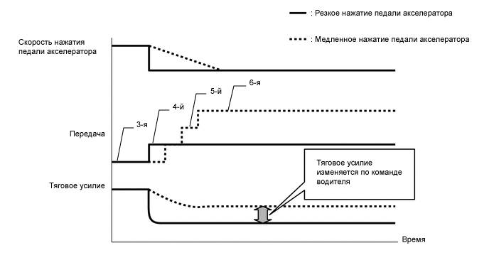
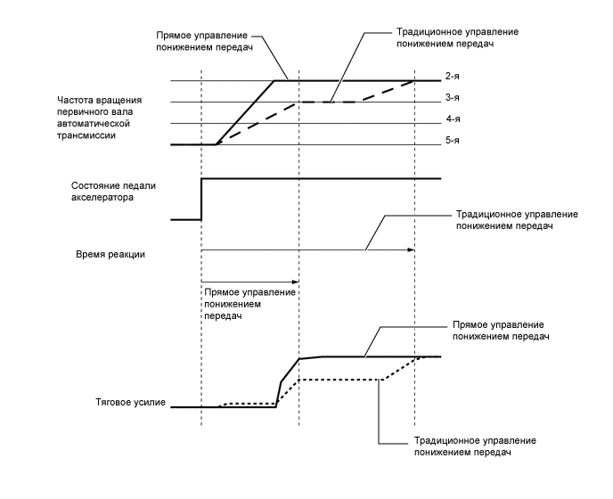
Direct Downshift Control
-
For conventional downshift control, when shifting from 6th to 3rd or 5th to 2nd, downshifts use an intermediate gear in order to achieve smooth acceleration response. In addition to conventional control, direct downshift control is used for this model. This control skips unnecessary shifts, enabling the vehicle to downshift directly from 6th to 3rd or from 5th to 2nd.
-
When the accelerator pedal is depressed quickly, direct downshift control enables direct downshifts with a quick shift response, skipping unnecessary shifts. Direct downshift control places the emphasis on reducing the time required to achieve the target gear. Conventional downshift control is used when the accelerator pedal is depressed slowly, providing smooth acceleration response. As a result, this logic achieves downshift responsiveness in accordance with the driver's intentions.
-
-
Lock-up Timing Control
-
The ECM uses lock-up timing control in order to improve fuel consumption performance in 2nd or higher when the shift lever is in D, or when the S6, S5 or S4 range is selected.
Lock-up Timing Control Operation Gear Position Shift Lever Position or Shift Range D or S6 S5 S4 1st X X X 2nd ○ ○ ○ 3rd ○ ○ ○ 4th ○ ○ ○ 5th ○ ○ - 6th ○ - - Tech Tips
○: Available
X: Not available
-: Not applicable
-
-
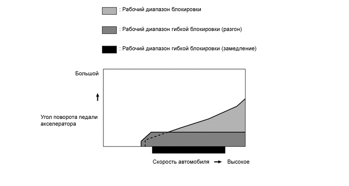
Flex Lock-up Clutch Control
-
During acceleration, partial control of the power transmission between the lock-up clutch and torque converter greatly boosts transmission efficiency in accordance with the driving conditions, improving fuel economy.
-
Even when the vehicle is decelerating (the accelerator pedal is released), flex lock-up clutch control operates. As a result, the fuel-cut area is expanded and fuel economy is improved.
-
By allowing flex lock-up clutch control to continue operating during gearshifts, smooth torque transmission is obtained. As a result, fuel economy and driveability are improved.
-
For flex lock-up clutch control, H infinity (H∞) control theory is used to achieve a high level of system stability and response to various characteristic changes.
Flex Lock-up Clutch Control Operation Gear Position Shift Lever Position or Shift Range D S6 S5 S4 1st X X X X 2nd ○ ○ ○ ○ 3rd ○ ○ ○ ○ 4th ○* ○* ○* ○* 5th ○* ○* ○* - 6th ○* ○* - - Tech Tips
○: Available
X: Not available
-: Not applicable
*: Flex lock-up clutch control also operates during deceleration.
-
-
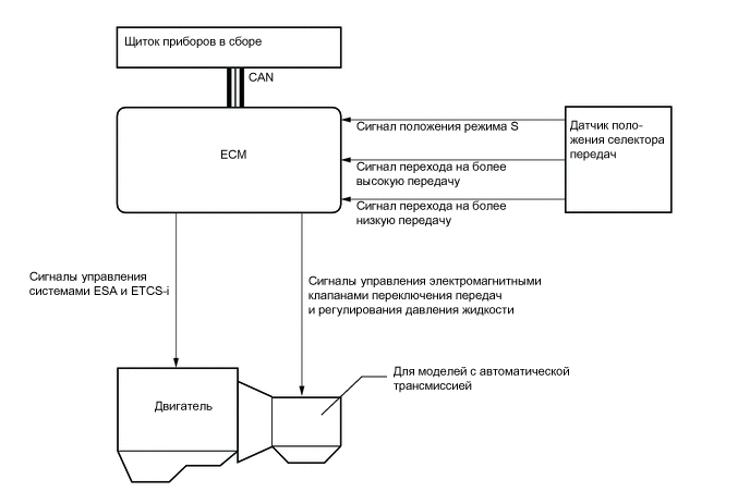
Multi-mode Automatic Transmission
-
The multi-mode automatic transmission is designed to allow the driver to switch between gear ranges. By moving the shift lever to S and then moving the shift lever toward "+" (forward) or to "-" (backward), the driver can select the desired shift range. Thus, the driver is able to shift gears with a manual-like feel.
-
This multi-mode automatic transmission is designed to allow the driver to switch gear ranges; it is not for manually selecting single gears.
-
When the vehicle is being driven at a speed that is higher than the maximum safe speed for a downshift, any attempt to shift to a lower range by operating the shift lever will not be performed. This is done in order to protect the automatic transaxle. In this case, the ECM sounds the buzzer in the combination meter assembly twice to alert the driver.
-
The driver can select S mode by moving the shift lever to S. At this time, the 4th or 5th shift range will be selected according to the vehicle speed (during AI-shift control, however, the 3rd shift range may be selected).
-
Under this control, the ECM performs shift control within the usable gear range that the driver selects. As with an ordinary automatic transaxle, the ECM shifts to 1st gear when the vehicle is stopped.
-
The shift lever position and the shift range are indicated by the shift indicator light in the combination meter assembly (the shift range is shown only when the shift lever is in S, and it is not shown when the shift lever is in P, R, N or D).
-
When the shift lever is in S, the S mode indicator light in the combination meter assembly illuminates. The shift indicator light indicates the shift range that the driver has selected.
-
Holding the shift lever toward "+" with the shift lever in S changes the shift range to the S6 range regardless of the current range (S1 to S5).
-
In order to prevent an excessive engine speed, a function is used that automatically selects a higher shift range before the engine speed becomes excessive.
-
In order to protect the automatic transaxle, a function is used that automatically selects a higher shift range when the fluid temperature is high.
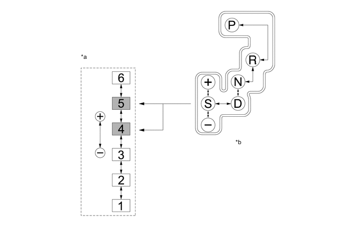
*a Transition of Shift Ranges *b Shift Pattern 
Default Shift Range - -
Usable Gear Chart Shift Range Shift Range Indicator Display Usable Gear S6 6 1st to 6th S5 5 1st to 5th S4 4 1st to 4th S3 3 1st to 3rd S2 2 1st to 2nd S1 1 1st -
-
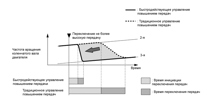
High Response Upshift Control
-
The high response upshift control achieves highly responsive upshift operation using clutch to clutch pressure control, which regulates each clutch and brake quickly and precisely, and by using the powertrain cooperative control, which optimally regulates engine torque during shifting.
-
When the shift lever is in D or S, the high response upshift control activates when Sport mode is selected.
-
-
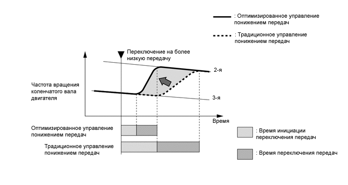
Blipping Downshift Control
-
The blipping downshift control regulates each clutch and brake using the clutch to clutch pressure control, allowing them to be engaged smoothly and disengaged quickly. In addition, fuel injection volume is increased and engine speed is boosted by the powertrain cooperative control, thus ensuring proper engine brake force. In this way, a smooth and quick downshift is achieved.
-
The blipping downshift control activates by downshifting with the shift lever in S when Sport mode is selected.
-
-
-
FUNCTION
-
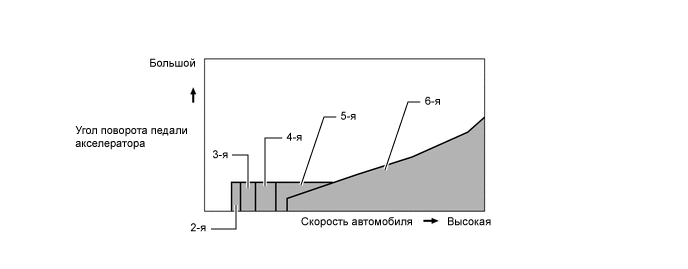
Shift Pattern Select System
-
The driver can select 2 different settings for the shift schedule and AI-shift control.
-
When the pattern select switch is on (Sport mode), a more aggressive shift schedule and AI-shift tuning are selected for sporty driving.
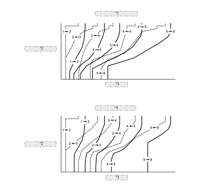
*1 Normal Mode Shift Pattern *2 Accelerator Pedal Depressing Angle *3 Vehicle Speed *4 Sport Mode Shift Pattern -
When Sport mode is selected with the shift lever in D, the shift schedule is changed to Sport and driver's intention support control, quick brake downshift control and high response upshift control are operated. As a result, the system determines the driver's intention, thus enabling a dynamic drive on winding roads even in the D range. In addition, when Sport mode is selected with the shift lever in S, the blipping down shift control is activated in addition to the controls mentioned above.
Control Condition Mode Normal Sport Shift Lever Position D, S D S Shift Schedule Normal Sport Sport Driver's Intention Support Control Normal Sport Sport Quick Brake Downshift Control - ○ ○ High Response Up Shift Control - ○ ○ Blipping Down Shift Control - - ○ Tech Tips
○: Applicable
-: Not applicable
-
-
-
FAIL-SAFE
-
The fail-safe function minimizes the loss of operability when an abnormality occurs in a sensor or a shift solenoid valve.
-
For details, refer to the Repair Manual.
-
-
DIAGNOSIS
-
When the ECM detects a malfunction, the ECM records the malfunction and memorizes the information related to the fault. Furthermore, the ECM illuminates or blinks the MIL in the combination meter to inform the driver.
-
The ECM will also store the Diagnostic Trouble Codes (DTCs) of the malfunctions. The DTCs stored in the ECM are output to the Global TechStream (GTS) via the DLC3.
-
For details, refer to the Repair Manual.
-