БЛОК ДВИГАТЕЛЯ
-
CONSTRUCTION
-
A cylinder block made of heat-treated aluminum alloy (AlSi9Cu3) is used.
-
This engine has cylinder liners. The gray cast iron liners are cast during the manufacture of the cylinder block. Dry liners are used that do not have any direct contact with the coolant. The coolant jacket is completely enclosed by the cylinder block sub-assembly casting.
-
The structure of the cylinder block is divided into different areas:
-
Deck
-
Bearing seat area (bearing seat and bearing cap)
-
Cylinder
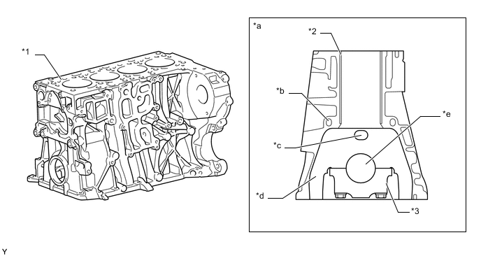
*1 Cylinder Block *2 Cylinder Liner *3 Crankshaft Bearing Cap - - *a Cross-section *b Oil Passage *c Ventilation Window (Opening) *d Bearing Seat *e Bore Hole for Crankshaft - - -
-
This engine is equipped with a closed-deck design cylinder block. In the case of the closed-deck design the cylinder block deck is to a large extent closed in the area around the cylinders. Openings are created in the form of bore holes and ducts for pressure oil, oil return, engine coolant, cylinder block sub-assembly ventilation and cylinder head bolts.
Tech Tips
The difference between a closed-deck design cylinder block and open-deck design is shown in the illustration.
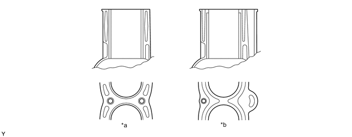
*a Closed-deck Design *b Open-deck Design -
The bearing seat area (bearing seat and bearing cap) absorbs the force applied to the crankshaft bearing.
-
The bearing seat is the upper half of a crankshaft bearing in the cylinder block sub-assembly. Bearing seats are always integrated in the cylinder block sub-assembly casting. This engine features ventilation windows in the bearing seats above the crankshaft. When the engine is running, the gas is continually kept moving in the crank space. The movements of the pistons act like pumps on the gas. The ventilation windows reduce pumping losses, since pressure compensation in the entire cylinder block sub-assembly is made easier.
-
The crankshaft bearing caps form the lower seal with the bearing seats and are bolted to the seats. During the processing of manufacturing the cylinder block sub-assembly bearing seat and crankshaft bearing cap are jointly machined. It is therefore absolutely essential to locate them in position in relation to each other.
-
This engine makes use of a relative new way of providing exact positioning. This involves an impression in the contact surface between the bearing seat and the crankshaft bearing cap. This method of location ensures that an absolutely smooth transition surface is maintained, even after renewed assembly, in the bore hole for the crankshaft bearing between the bearing seat and the crankshaft bearing cap. When the impression connection is made the crankshaft bearing cap is designed with a profile. When the crankshaft bearing bolts are tightened for the first time, this profile is impressed into the cylinder block sub-assembly-side bearing seat surface and facilitates positive locking in the engine transversal and longitudinal directions.
-
To ensure positive locking in the engine longitudinal direction, the profile must be shorter than the cylinder block sub-assembly-side contact surface. Thus the profile does not protrude, but instead has a stop. In order not to make the bearing seat wider than is necessary, the crankshaft bearing cap is slightly constricted in the area of the profile. 2 profile elements per contact surface are used. The crankshaft bearing cap is made from very strong sintered iron.
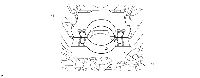
*1 Crankshaft Bearing Cap - - *a Bearing Seat - -
-