БЛОК ДВИГАТЕЛЯ
-
CONSTRUCTION
-
A cylinder head cover made of plastic is used for weight reduction.
-
In addition, the plastic cylinder head cover has excellent noise insulation characteristics.
-
An oil filler neck, a pressure control valve and a spring tab oil separator are placed on the cylinder head cover.
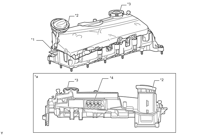
*1 Cylinder Head Cover Sub-assembly *2 Oil Filler Neck *3 Pressure Control Valve *4 Spring Tab Oil Separator *a Cross Section - - -
The spring tab oil separator separates the engine oil from the blow-by gas.
-
The spring tabs are pressed by the blow-by gas, allowing the blow-by gas to flow past. Because the opening cross-section is relatively small, the blow-by gas flowing past is greatly sped up. The pretensioned metal spring tabs (gap separators) regulate the speed of the air mass flow and thus ensure optimum oil separation of the blow-by gas at every operating point. Because the blow-by gas is then diverted approximately 180°, the oil contained in the blow-by gas is thrown against the surrounding walls and flows along these walls through a bore back into the oil pan sub-assembly.
-
The degree that the spring tabs are opened depends on the quantity of blow-by gas, which results in optimum oil separation regardless of the blow-by gas throughput. The spring tab separator has made it possible to increase the separation quality under all operating conditions, but above all when the blow-by gas throughput is low. The separated engine oil flows back into the oil pan sub-assembly. The cleaned blow-by gas flows through the pressure control valve into the intake pipe ahead of the exhaust turbocharger.
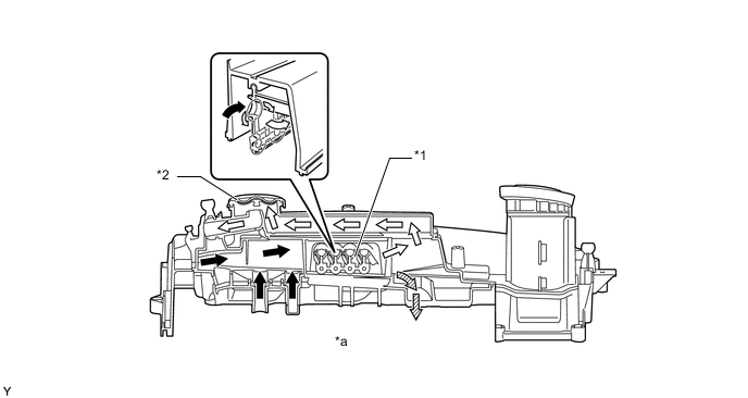
*1 Spring Tab Oil Separator *2 Pressure Control Valve *a Cylinder Head Cover Sub-assembly Cross-section - - 
Blow-by Gas Mixed with Oil 
Blow-by Gas Cleaned by Oil 
Oil Droplets - -
-
-
The pressure control valve maintains a constant vacuum in the cylinder block sub-assembly.
-
When the engine is stopped, the pressure control valve is open. Ambient pressure is applied on both sides of the diaphragm. The diaphragm is fully opened by means of spring force.
-
When the engine is started, the vacuum in the intake pipe increases and the pressure control valve closes. This state is obtained primarily at idle or in coasting (overrun) mode, since only minimal or no blow-by gas is produced. A high vacuum (relative to the ambient pressure) is therefore applied on the inside of the diaphragm. In this way, the ambient pressure which is applied on the outside of the diaphragm closes the valve that is resisting the force of the spring.
-
Blow-by gas is produced by load and engine revs. The blow-by gas reduces the relative vacuum acting on the diaphragm. The compression spring is able to open the valve to allow blow-by gas to be drawn in. The valve continues to open until an equilibrium between the ambient pressure and the cylinder block sub-assembly vacuum plus spring force is obtained. The more blow-by gases are produced, the lower the relative vacuum acting on the inside of the diaphragm and the wider the pressure control valve opens. In this way, a fixed vacuum is maintained in the cylinder block sub-assembly.
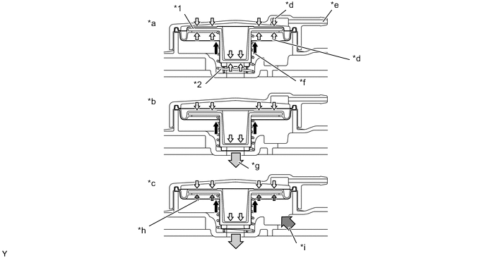
*1 Diaphragm *2 Compression Spring *a Pressure Control Valve Open with Engine Stopped *b Pressure Control Valve Closed with Maximum Vacuum in Cylinder Block Sub-assembly *c Pressure Control Valve Open with Vacuum in Cylinder Block Sub-assembly Too Low *d Ambient Pressure *e Connection to Ambient Pressure *f Spring Force of Compression Spring *g Intake Manifold Vacuum *h Effective Vacuum in Cylinder Block Sub-assembly *i Blow-by Gas from Cylinder Block Sub-assembly - -
-
-