БЛОК ДВИГАТЕЛЯ
-
CONSTRUCTION
-
Each controller consists of a housing driven by the timing chain and a vane coupled with the intake or exhaust camshaft.
-
Both the intake and exhaust sides have a 4-blade vane.
-
The oil pressure sent from the advanced or retarded side path at the intake and exhaust camshafts causes rotation in the VVT-i controller vane circumferential direction to vary the intake and exhaust valve timing continuously.
-
When the engine is stopped, a lock pin locks the intake camshaft at the most retarded end and the exhaust camshaft at the most advanced end to ensure that the engine starts properly.
-
An advance assist spring is provided on the exhaust side VVT-i controller. This spring applies torque in the advance direction when the engine is stopped, thus ensuring the engagement of the lock pin.
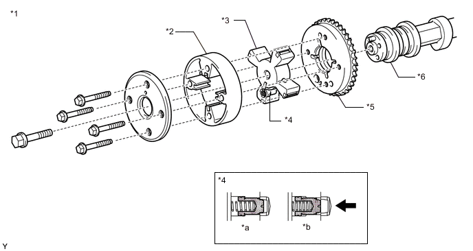
*1 Intake Side VVT-i Controller *2 Housing *3 Vane (Fixed on Intake Camshaft) *4 Lock Pin *5 Sprocket *6 Intake Camshaft *a At a Stop *b In Operation 
Oil Pressure - - 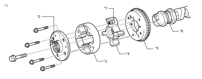
*1 Exhaust Side VVT-i Controller *2 Advance Assist Spring *3 Housing *4 Vane (Fixed on Exhaust Camshaft) *5 Sprocket *6 Exhaust Camshaft *7 Lock Pin - -
-