AIR CONDITIONING SYSTEM
-
OPERATION
-
Mode Position and Door Operation
Tech Tips
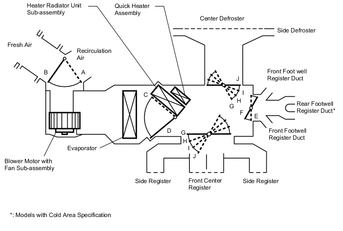
This illustration is a model diagram showing the door positions in each mode. The parts layout and the number of the doors in the illustration are different from those of the actual system.
Control Damper Operation Position Damper Position Operation Air Inlet FRESH A Brings in fresh air. RECIRCULATION B Recirculates internal air. Air Mix MAX COLD to MAX HOT C to D Varies the mixture ratio of the fresh air and the recirculation air in order to regulate the temperature continuously from HOT to COLD. Mode 
FACE E, J Air blows out of the center register and side registers. 
BI-LEVEL F, J Air blows out of the center register, side registers, and front and rear footwell register ducts. 
FOOT F, I Air blows out of the front and rear footwell register ducts and side registers. In addition, air blows out slightly from the front defroster and side defrosters. 
FOOT/DEF F, H Defrosts the windshield through the center defroster, side defrosters and side registers, while air is also blown out from the front and rear footwell register ducts. 
DEF E, G Defrosts the windshield through the center defroster, side defrosters and side registers. -
Air Outlets and Airflow Volume
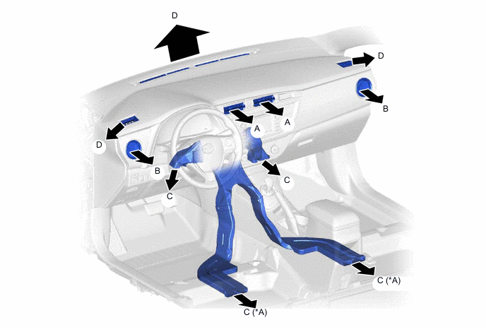
*A Models with Cold Area Specification - - Indication Mode A B C D Center Side Foot Defroster FACE 
- - BI-LEVEL 

- FOOT - 
FOOT/DEF - DEF - - Tech Tips
The size of the circle ○ indicates the proportion of airflow volume.
-