ENTRY AND START SYSTEM
Figure 1. Start Function
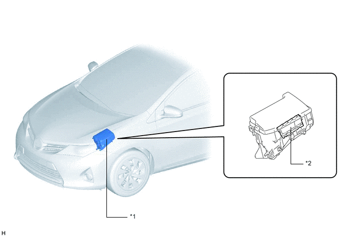
| *1 | Engine Room Relay Block and Junction Block Assembly | *2 | No. 1 integration Relay - IG2 Relay |
Figure 2. Hatchback Models with Start Function
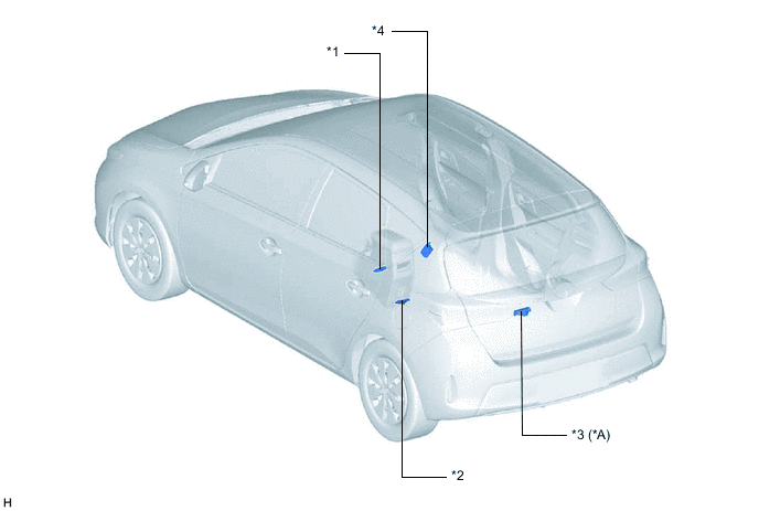
| *A | Except LHD Models without Entry Function | - | - |
| *1 | No. 3 Indoor Electrical Key Antenna Assembly (Front) | *2 | No. 2 Indoor Electrical Key Antenna Assembly (Center) |
| *3 | No. 1 Indoor Electrical Key Antenna Assembly (Rear) | *4 | Door Control Receiver |
Figure 3. Wagon Models with Start Function
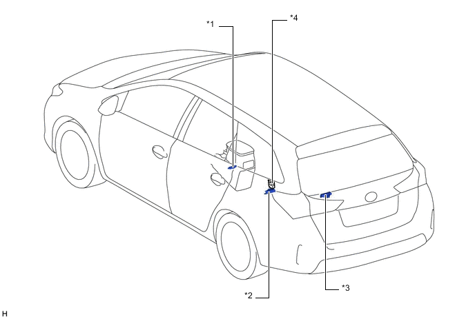
| *1 | No. 3 Indoor Electrical Key Antenna Assembly (Front) | *2 | No. 2 Indoor Electrical Key Antenna Assembly (Center) |
| *3 | No. 1 Indoor Electrical Key Antenna Assembly (Rear) | *4 | Door Control Receiver |
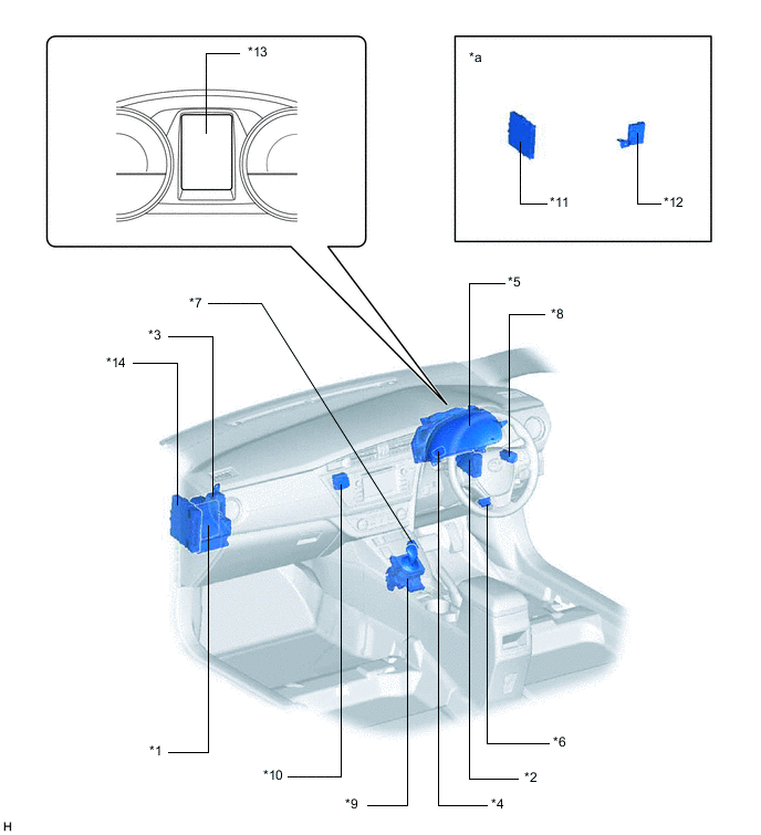
Figure 4. LHD Models with Start Function
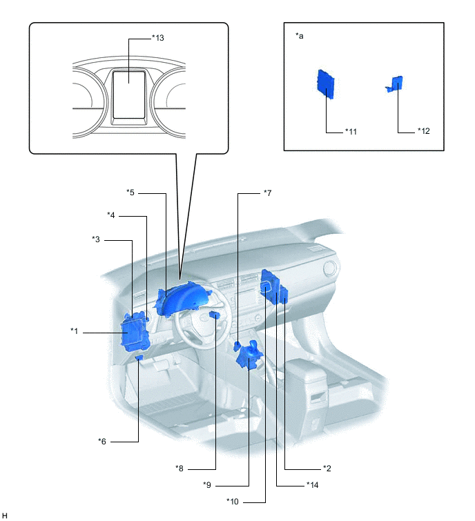
| *1 | Main Body ECU (Multiplex Network Body ECU) | *2 | Transmission Control ECU Assembly |
| *3 | Instrument Panel Junction Block Assembly - ACC Relay - IG1 Relay |
*4 | Stop Light Switch Assembly |
| *5 | Combination Meter Assembly | *6 | DLC3 |
| *7 | Transmission Shift Main Switch | *8 | Power Switch |
| *9 | Transmission Floor Shift Assembly | *10 | Telltale Light Assembly - Security Indicator Light |
| *11 | Certification ECU (Smart Key ECU Assembly) | *12 | ID Code Box (Immobiliser Code ECU) |
| *13 | Multi-information Display | *14 | Power Management Control ECU |
| *a | Refer to Service Bulletin for the installation position of the parts. | - | - |
Figure 5. RHD Models with Start Function
| *1 | Main Body ECU (Multiplex Network Body ECU) | *2 | Transmission Control ECU Assembly |
| *3 | Instrument Panel Junction Block Assembly - ACC Relay - IG1 Relay |
*4 | Stop Light Switch Assembly |
| *5 | Combination Meter Assembly | *6 | DLC3 |
| *7 | Transmission Shift Main Switch | *8 | Power Switch |
| *9 | Transmission Floor Shift Assembly | *10 | Telltale Light Assembly - Security Indicator Light |
| *11 | Certification ECU (Smart Key ECU Assembly) | *12 | ID Code Box (Immobiliser Code ECU) |
| *13 | Multi-information Display | *14 | Power Management Control ECU |
| *a | Refer to Service Bulletin for the installation position of the parts. | - | - |
Figure 6. Hatchback Models with Entry Function
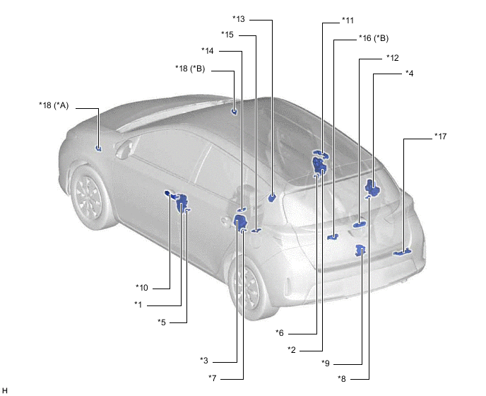
| *A | LHD Models | *B | RHD Models |
| *1 | Front Door Lock Assembly LH | *2 | Front Door Lock Assembly RH |
| *3 | Rear Door Lock Assembly LH | *4 | Rear Door Lock Assembly RH |
| *5 | Front Door Courtesy Light Switch Assembly (LH) | *6 | Front Door Courtesy Light Switch Assembly (RH) |
| *7 | Rear Door Courtesy Light Switch Assembly (LH) | *8 | Rear Door Courtesy Light Switch Assembly (RH) |
| *9 | Back Door Lock Assembly | *10 | Front Door Outside Handle Assembly LH |
| *11 | Front Door Outside Handle Assembly RH | *12 | Back Door Opener Switch Assembly |
| *13 | Door Control Receiver | *14 | No. 3 Indoor Electrical Key Antenna Assembly (Front) |
| *15 | No. 2 Indoor Electrical Key Antenna Assembly (Center) | *16 | No. 1 Indoor Electrical Key Antenna Assembly (Rear) |
| *17 | Electrical Key Antenna | *18 | Wireless Door Lock Buzzer |
Figure 7. Wagon Models with Entry Function
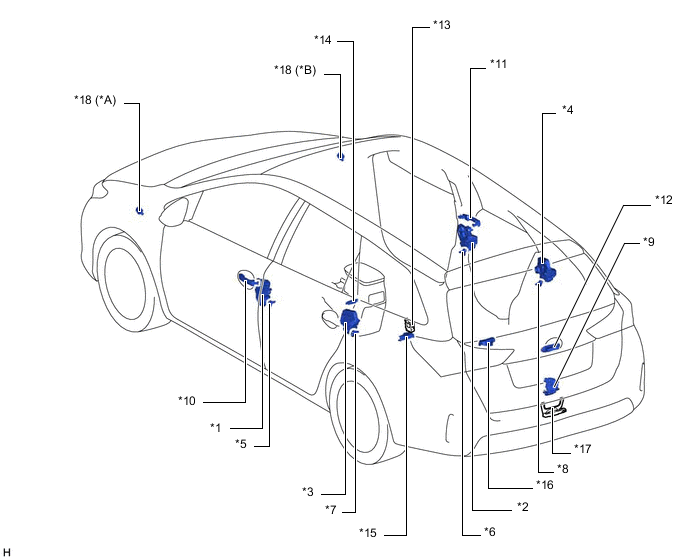
| *A | LHD Models | *B | RHD Models |
| *1 | Front Door Lock Assembly LH | *2 | Front Door Lock Assembly RH |
| *3 | Rear Door Lock Assembly LH | *4 | Rear Door Lock Assembly RH |
| *5 | Front Door Courtesy Light Switch Assembly (LH) | *6 | Front Door Courtesy Light Switch Assembly (RH) |
| *7 | Rear Door Courtesy Light Switch Assembly (LH) | *8 | Rear Door Courtesy Light Switch Assembly (RH) |
| *9 | Back Door Lock Assembly | *10 | Front Door Outside Handle Assembly LH |
| *11 | Front Door Outside Handle Assembly RH | *12 | Back Door Opener Switch Assembly |
| *13 | Door Control Receiver | *14 | No. 3 Indoor Electrical Key Antenna Assembly (Front) |
| *15 | No. 2 Indoor Electrical Key Antenna Assembly (Center) | *16 | No. 1 Indoor Electrical Key Antenna Assembly (Rear) |
| *17 | Electrical Key Antenna | *18 | Wireless Door Lock Buzzer |
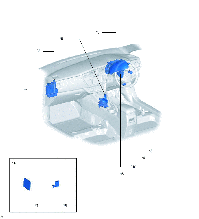
Figure 8. LHD Models with Entry Function
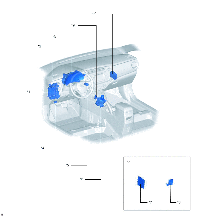
| *1 | Main Body ECU (Multiplex Network Body ECU) | *2 | Instrument Panel Junction Block Assembly - ACC Relay - IG1 Relay |
| *3 | Combination Meter Assembly | *4 | DLC3 |
| *5 | Power Switch | *6 | Transmission Floor Shift Assembly |
| *7 | Certification ECU (Smart Key ECU Assembly) | *8 | ID Code Box (Immobiliser Code ECU) |
| *9 | Transmission Shift Main Switch | *10 | Transmission Control ECU Assembly |
| *a | Refer to Service Bulletin for the installation position of the parts. | - | - |
Figure 9. RHD Models with Entry Function
| *1 | Main Body ECU (Multiplex Network Body ECU) | *2 | Instrument Panel Junction Block Assembly - ACC Relay - IG1 Relay |
| *3 | Combination Meter Assembly | *4 | DLC3 |
| *5 | Power Switch | *6 | Transmission Floor Shift Assembly |
| *7 | Certification ECU (Smart Key ECU Assembly) | *8 | ID Code Box (Immobiliser Code ECU) |
| *9 | Transmission Shift Main Switch | *10 | Transmission Control ECU Assembly |
| *a | Refer to Service Bulletin for the installation position of the parts. | - | - |