TOYOTA PARKING ASSIST-SENSOR SYSTEM(except Hatchback)
-
FUNCTION OF MAIN COMPONENTS
Component Function No. 1/No. 2/No. 4 Ultrasonic Sensor (10) Detects the distance between the vehicle and an obstacle. No. 1 Clearance Warning Buzzer (Front) Sounds to inform the driver according to the distance to the obstacle. No. 2 Clearance Warning Buzzer (Rear) Combination Meter Assembly Multi-information Display
-
Displays the location of the obstacle and the approximate distance between the vehicle and the obstacle.
-
Displays an indication of a malfunction or freezing of an ultrasonic sensor to inform the driver.
Master Warning Light Illuminates in accordance with the indication on the multi-information display. Back Sonar or Clearance Sonar Switch Assembly Operating this switch allows the operation of the TOYOTA parking assist-sensor system to be enabled or disabled. Clearance Warning ECU Assembly
-
Judges the approximate distance between the vehicle and an obstacle based on signals from the ultrasonic sensors. Output signals are sent to the multi-information display.
-
Sounds the No. 1 or No. 2 clearance warning buzzer.
Air Conditioning Amplifier Assembly Sends outside temperature information to the clearance warning ECU assembly to adjust the distance rate from the ultrasonic sensors. Transmission Floor Shift Assembly
- Shift Lever Position Sensor
Sends the shift state signals to the power management control ECU. Power Management Control ECU
-
Transmits the shift state signals to the clearance warning ECU assembly.
-
Transmits data between CAN V bus and CAN sub bus 11.
Brake Booster with Master Cylinder Assembly
- Skid Control ECU
Sends the wheel speed signal to the clearance warning ECU assembly. -
-
FUNCTION
-
The operating condition of each sensor differs according to its installed position as shown in the table below:
Installation Position Operating Condition Front Corner
-
Power switch is on (IG).
-
System is activated.*
-
Shift state other than park (P) is selected.
-
Vehicle speed is approximately 10 km/h (6 mph) or less.
Front Center Front Side Rear Corner
-
Power switch is on (IG).
-
System is activated.*
-
Reverse (R) is selected.
Rear Center *: Even if the back sonar or clearance sonar switch assembly is off, the system is activated when the simple intelligent parking assist system is operating.
-
-
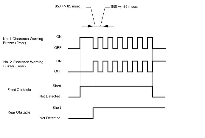
No. 1/No. 2 Clearance Warning Buzzer
-
Depending on the detection distance and the detection area, the sound pattern of the No. 1 clearance warning buzzer will vary.
Detection Area Detection Distance (mm (in.)) Buzzer Sound Pattern On (msec.) Off (msec.) Front Corner Long 500 +/- 50 to 375 +/- 37.5 (19.7 +/- 2.0 to 14.8 +/- 1.5) 150 +/- 15 150 +/- 15 Middle 375 +/- 37.5 to 250 +/- 25 (14.8 +/- 1.5 to 9.8 +/- 1.0) 75 +/- 7.5 75 +/- 7.5 Short 250 +/- 25 or less (9.8 +/- 1.0 or less) Continuous Sound 0 Front Center Longest 1000 +/- 100 to 550 +/- 55 (39.4 +/- 3.9 to 21.7 +/- 2.2) 150 +/- 15 650 +/- 15 Long 550 +/- 55 to 425 +/- 42.5 (21.7 +/- 2.2 to 16.7 +/- 1.7) 150 +/- 15 150 +/- 15 Middle 425 +/- 42.5 to 300 +/- 30 (16.7 +/- 1.7 to 11.8 +/- 1.2)*1 75 +/- 7.5 75 +/- 7.5 425 +/- 42.5 to 250 +/- 25 (16.7 +/- 1.7 to 9.8 +/- 1.0)*2 Short 300 +/- 30 or less (11.8 +/- 1.2 or less)*1 Continuous Sound 0 250 +/- 25 or less (9.8 +/- 1.0 or less)*2 Front Side Short 250 +/- 25 or less (9.8 +/- 1.0 or less) Continuous Sound 0 *1: While the simple intelligent parking assist system is not operating
*2: While the simple intelligent parking assist system is operating
-
Depending on the detection distance and the detection area, the sound pattern of the No. 2 clearance warning buzzer will vary.
Detection Area Detection Distance (mm (in.)) Buzzer Sound Pattern On (msec.) Off (msec.) Rear Corner Long 500 +/- 50 to 375 +/- 37.5 (19.7 +/- 2.0 to 14.8 +/- 1.5) 150 +/- 15 150 +/- 15 Middle 375 +/- 37.5 to 250 +/- 25 (14.8 +/- 1.5 to 9.8 +/- 1.0) 75 +/- 7.5 75 +/- 7.5 Short 250 +/- 25 or less (9.8 +/- 1.0 or less) Continuous Sound 0 Rear Center Longest 1500 +/- 150 to 550 +/- 55 (59.1 +/- 5.9 to 21.7 +/- 2.2) 150 +/- 1.5 650 +/- 65 Long 550 +/- 55 to 425 +/- 42.5 (21.7 +/- 2.2 to 16.7 +/- 1.7) 150 +/- 1.5 150 +/- 1.5 Middle 425 +/- 42.5 to 300 +/- 30 (16.7 +/- 1.7 to 11.8 +/- 1.2)*1 75 +/- 7.5 75 +/- 7.5 425 +/- 42.5 to 250 +/- 25 (16.7 +/- 1.7 to 9.8 +/- 1.0)*2 Short 300 +/- 30 or less (11.8 +/- 1.2 or less)*1 Continuous Sound 0 250 +/- 25 or less (9.8 +/- 1.0 or less)*2 *1: While the simple intelligent parking assist system is not operating
*2: While the simple intelligent parking assist system is operating
-
The ultrasonic sensors are divided into 2 groups: a front section group (front corners, front center and front sides) and a rear section group (rear corners and rear center). If multiple ultrasonic sensors detect obstructions at the same time, the No. 1/No. 2 clearance warning buzzer sounds as follows, in accordance with the detection distance and detection area of each group:
Buzzer Sound Pattern ON/OFF Time (msec.) Detection Distance Front Section Short Middle Long Longest Not detected Rear Section Short Timing 1 Continuous Sound (Rear) Continuous Sound (Rear) Continuous Sound (Rear) Continuous Sound (Rear) Middle Continuous Sound (Front) 75/75 (*) 75/75 (Rear) 75/75 (Rear) 75/75 (Rear) Long Continuous Sound (Front) 75/75 (Front) 150/150 (*) 150/150 (Rear) 150/150 (Rear) Longest Continuous Sound (Front) 75/75 (Front) 150/150 (Front) 150/650 (*) 150/650 (Rear) Not detected Continuous Sound (Front) 75/75 (Front) 150/150 (Front) 150/650 (Front) None *: The buzzer of the front or rear sensor, which is closest to the obstacle, sounds.
Figure 1. Timing 1
-
-
Multi-information Display
-
The location of an obstacle and the approximate distance between the vehicle and the obstacle are displayed on the multi-information display.
-
The number of lines shown on the display changes based on the actual distance and flashes when the distance is short.
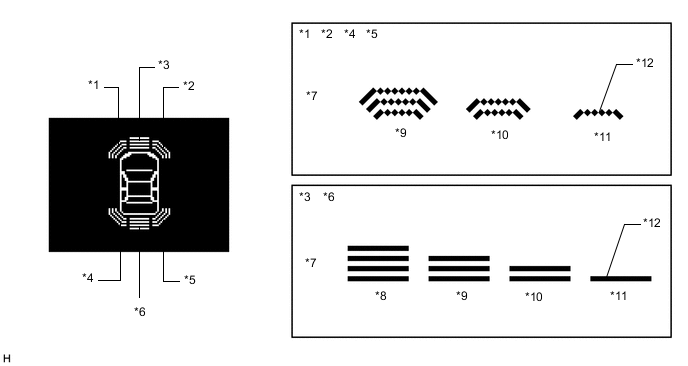
*1 Front Corner LH/Front Side LH *2 Front Corner RH/Front Side RH *3 Front Center *4 Rear Corner LH *5 Rear Corner RH *6 Rear Center *7 Distance *8 Longest *9 Long *10 Middle *11 Short *12 Flashes -
A screen displaying a warning message indicating an ultrasonic sensor malfunction, ultrasonic sensor freezing, or presence of foreign matter on the ultrasonic sensor, is displayed on the multi-information display. The warning message appears in the same language that has been selected by the language selector of the multi-information display.

-
-
Detection Area
-
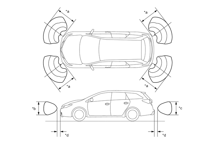
The detection areas of the ultrasonic sensor are as shown in the following illustration.
-
These detection areas are applicable when positioning a 60 mm (2.36 in.) diameter pole parallel or perpendicular to the ground. The ranges vary depending on the measuring method and type of obstacle.
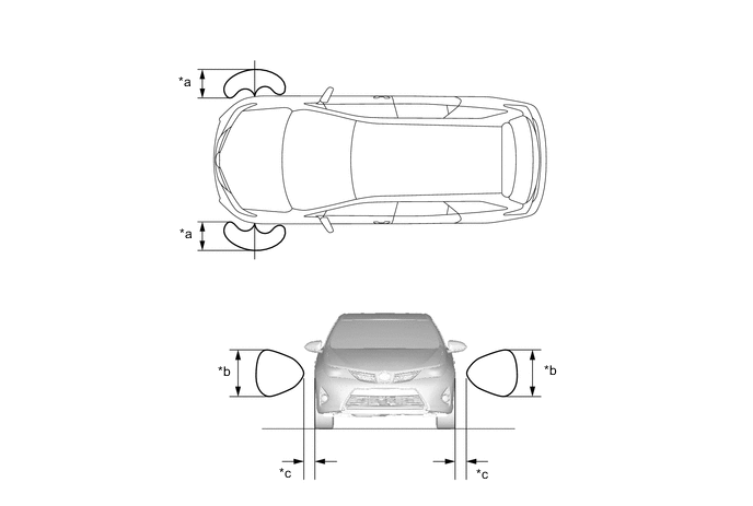
Figure 2. Corners
*a Approximately 500 mm (19.7 in.) *b Approximately 650 mm (25.6 in.) *c Approximately 550 mm (21.7 in.) *d Approximately 100 mm (3.9 in.) Figure 3. Center
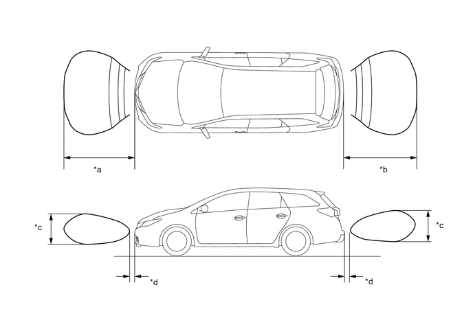
*a Approximately 1000 mm (39.4 in.) *b Approximately 1500 mm (59.1 in.) *c Approximately 650 mm (25.6 in.) *d Approximately 100 mm (3.9 in.) Figure 4. Sides
*a Approximately 250 mm (9.8 in.) *b Approximately 400 mm (15.7 in.) *c Approximately 100 mm (3.9 in.) - -
-
-
-
DIAGNOSIS
-
If a system malfunction is detected, the clearance warning ECU assembly stores Diagnostic Trouble Codes (DTCs) in its memory. For details, refer to the Repair Manual.
-