BRAKE CONTROL SYSTEM
-
FUNCTION OF MAIN COMPONENTS
Component Function Brake Booster Pump Assembly
-
Consists of a pump, pump motor and accumulator. The hydraulic power source portion generates and stores the hydraulic pressure, which the skid control ECU uses for controlling braking.
-
A relief valve is installed in the hydraulic brake booster.
-
An accumulator pressure sensor (Pacc) is installed in the brake actuator.
Brake Booster with Master Cylinder Assembly Brake Actuator
-
Consists of 4 switching solenoid valves, 2 linear solenoid valves, 8 control solenoid valves.
-
Changes the brake fluid path based on the signals from the skid control ECU during operation of the ABS with EBD, Brake Assist, TRC, VSC+, and Hill-start Assist Control in order to control the fluid pressure that is applied to the wheel cylinders.
Hydraulic Brake Booster
-
Generates hydraulic pressure in accordance with the amount of effort applied to the brake pedal by the driver.
-
When a malfunction occurs in the brake system, the hydraulic brake booster supplies the fluid pressure (which is generated by brake pedal effort) directly to the wheel cylinders.
Relief Valve Returns the brake fluid to the reservoir tank to prevent excessive pressure if the pump operates continuously due to a malfunction of the accumulator pressure sensor (Pacc). Brake Pedal Stroke Simulator Generates a pedal stroke during braking in accordance with the driver's pedal effort. Skid Control ECU
-
Monitors the driving conditions of the vehicle in accordance with the signals received from the sensors and through cooperative control with the power management control ECU and power steering ECU assembly calculates the required amount of braking force, and controls the brake actuator.
-
Judges the vehicle driving condition based on signals from each sensor, and controls ABS with EBD, Brake Assist, TRC, VSC+, and Hill-start Assist Control.
-
Operates the brake booster pump assembly to control accumulator pressure based on accumulator pressure sensor signal.
Brake Booster with Master Cylinder Assembly Brake Fluid Level Warning Switch Detects a low brake fluid level. Stop Light Switch Assembly Detects the brake pedal being depressed and transmits its signal to the skid control ECU. Brake Pedal Stroke Sensor Assembly Directly detects the extent of the brake pedal stroke operated by the driver. Speed Sensor Detects the wheel speed of the 4 wheels. Airbag Sensor Assembly
-
Detects the vehicle's yaw rate.
-
Detects the vehicle's acceleration in the forward, rearward and lateral directions.
Spiral Cable with Sensor Assembly Steering Sensor Detects the steering direction and angle of the steering wheel. Combination Meter Assembly ABS Warning Light Lights up to alert the driver when the skid control ECU detects a malfunction in the ABS, EBD or Brake Assist. Brake Warning Light / Yellow (Minor Malfunction) Lights up to alert the driver when a minor malfunction is detected in the brake system, which does not affect the braking force (such as a malfunction in the regenerative brake). Brake Warning Light / Red (Malfunction)
-
Lights up to alert the driver when the skid control ECU detects a malfunction in the apportioning of the brake.
-
Lights up to inform the driver when the parking brake is on or the brake fluid level is low.
Slip Indicator Light
-
Blinks to inform the driver when the ABS, TRC, VSC or Hill-start Assist Control is operated.
-
Lights up to alert the driver in the event of malfunction of the TRC or VSC.
Buzzer
-
This buzzer sounds continuously to inform the driver when there is a malfunction in the hydraulic pressure circuit or a failure in the power supply.
-
Emits a warning sound to inform the driver when Hill-start Assist Control operation is started or finished.
Solenoid Relay (Built into the Skid Control ECU) Supply or cut off power to solenoid valves in the brake actuator. Motor Relays (Built into the Skid Control ECU) Normally supplies power to the pump motor using 2 out of 3 relays. Ensures power to the pump motor by using the rest relay if the skid control ECU malfunctions. Power Management Control ECU
-
Actuates the regenerative brake on receiving signal from the skid control ECU.
-
Sends the actual regenerative brake control value to the skid control ECU.
-
Controls the motive force based on an output control request signal received from the skid control ECU while the VSC or TRC is operating.
Power Steering ECU Assembly Operates cooperatively with the skid control ECU to control the steering assist torque. Hazard Warning Signal Switch Assembly Transmits a hazard warning light on/off request signal to the combination meter assembly. -
-
SYSTEM CONTROL
-
Control List
-
The brake control system has the following controls:
Control Outline Electronically Controlled Brake System Upon receiving signals from the skid control ECU, this system effects hydraulic pressure control at the 4 wheels. Regenerative Brake Cooperative Control Controls hydraulic braking in order to recover electrical energy by utilizing the regenerative brake of the hybrid system as much as possible. Anti-lock Brake System (ABS) The ABS helps prevent the wheels from locking when the brakes are applied firmly or when braking on a slippery surface. Electronic Brake Force Distribution (EBD) The EBD control utilizes ABS, realizing proper brake force distribution between the front and rear wheels in accordance with the driving conditions. In addition, during braking while cornering, it also controls the brake forces of the right and left wheels, helping maintain vehicle behavior. Brake Assist The primary purpose of Brake Assist is to provide an auxiliary brake force to assist a driver who cannot generate a large brake force during emergency braking, thus helping ensure the vehicle's braking performance. Traction Control (TRC) The TRC helps restrain the slippage of the drive wheels if the driver depresses the accelerator pedal excessively when starting off or accelerating on a slippery surface. Vehicle Stability Control (VSC) The VSC helps restrain sideways slippage of the vehicle during a strong front wheel skid or strong rear wheel skid, during cornering. VSC+ Effects cooperative control with the power steering ECU assembly in order to provide steering assist in accordance with the operating conditions of the vehicle. Hill-start Assist Control When starting uphill, this control maintains the brake hydraulic pressure to the 4 wheels, in order to momentarily prevent the vehicle from descending backward. Motive Force Control during TRC or VSC Operation Transmits a motive force control signal from the skid control ECU to the power management control ECU to limit the motive force while the TRC or VSC is being activated. Emergency Brake Signal In the case of emergency braking, the emergency brake signal flashes the hazard warning lights to alert the drivers in following vehicles.
-
-
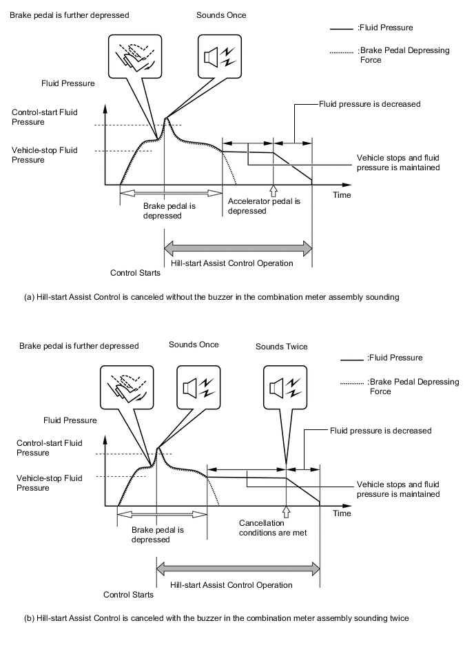
Hill-start Assist Control
-
The skid control ECU starts Hill-start Assist Control operation when the operating conditions below are met and the driver further depresses the brake pedal, causing the hydraulic pressure to exceed the control-start hydraulic pressure.
-
When Hill-start Assist Control operation starts, the buzzer in the combination meter assembly will sound once.
Hill-start Assist Control Operation Condition
-
The shift position is in any position other than P.
-
The accelerator pedal is not depressed.
-
The vehicle is at a standstill.
-
The parking brake is not applied.
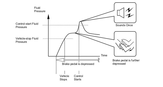
-
-
If any one of the below conditions is met during Hill-start Assist Control operation, Hill-start Assist Control will be canceled causing the slip indicator light to turn off.
-
The buzzer in the combination meter assembly sounds twice if the Hill-start Assist Control is canceled.
Conditions which cause Hill-start Assist Control operation to be canceled a) Buzzer in combination meter assembly does not sound
-
The driver depresses the accelerator pedal.
b) Buzzer in combination meter assembly sounds twice
-
The driver changes the shift position to P.
-
The driver depresses the parking brake pedal.
-
The driver depresses the brake pedal.
-
The driver releases the brake pedal for several seconds.
-
The driver keeps the brake pedal depressed continually for 3 minutes.
-
-
-
-
FAIL-SAFE
-
Brake System
-
When the brake actuator stops, the switching solenoid valves (SSC) and (SCC) close and the switching solenoid valves (SMC) and (SRC) open. Thus, the fluid pressure generated in the hydraulic brake booster by the driver's brake pedal operation is directly supplied to each of the wheel cylinders.
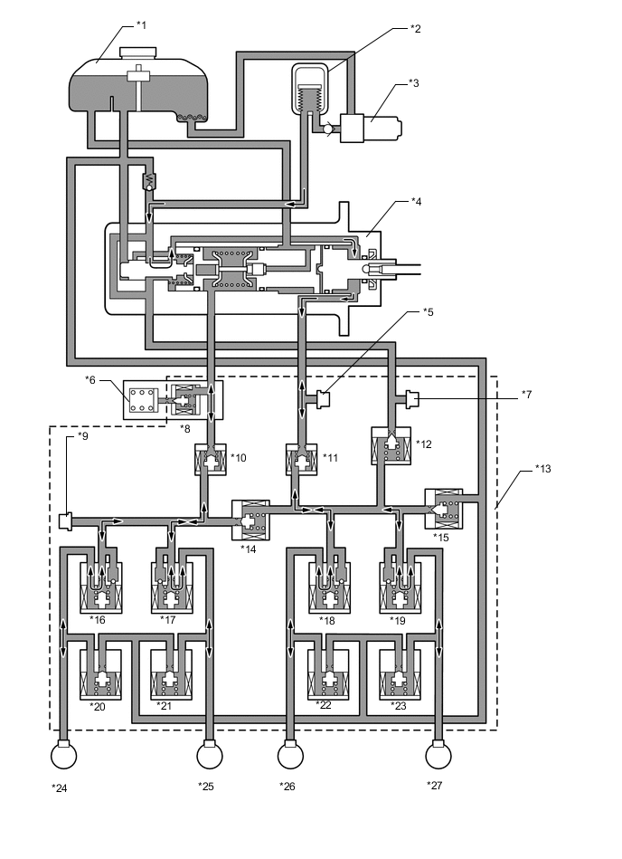
*1 Reservoir Tank *2 Accumulator *3 Pump Motor *4 Hydraulic Brake Booster *5 Master Cylinder Pressure Sensor *6 Stroke Simulator *7 Accumulator Pressure Sensor (Pacc) *8 Switching Solenoid Valve (SSC) *9 Front Wheel Cylinder Pressure Sensor *10 Switching Solenoid Valve (SMC) *11 Switching Solenoid Valve (SRC) *12 Linear Solenoid Valve (SLA) *13 Brake Actuator *14 Switching Solenoid Valve (SCC) *15 Linear Solenoid Valve (SLR) *16 Pressure Holding Solenoid Valve (FLH) *17 Pressure Holding Solenoid Valve (FRH) *18 Pressure Holding Solenoid Valve (RLH) *19 Pressure Holding Solenoid Valve (RRH) *20 Pressure Reduction Solenoid Valve (FLR) *21 Pressure Reduction Solenoid Valve (FRR) *22 Pressure Reduction Solenoid Valve (RLR) *23 Pressure Reduction Solenoid Valve (RRR) *24 Front Left Wheel Cylinder *25 Front Right Wheel Cylinder *26 Rear Left Wheel Cylinder *27 Rear Right Wheel Cylinder - - Item System Off Linear Solenoid Valve SLA Off (Close) SLR Off (Close) Switching Solenoid Valve SSC Off (Close) SCC Off (Close) SMC Off (Open) SRC Off (Open) Control Solenoid Valve FLH Off (Open) FRH Off (Open) RLH Off (Open) RRH Off (Open) FLR Off (Close) FRR Off (Close) RLR Off (Close) RRR Off (Close) -
When the accumulator pressure is not supplied due to a failure in the brake system, the skid control ECU closes the switching solenoid valves (SSC) and (SCC) and opens the switching solenoid valves (SMC) and (SRC). At this time, the fluid pressure generated in the master cylinder chamber of the hydraulic brake booster is supplied only to the front wheel cylinders.
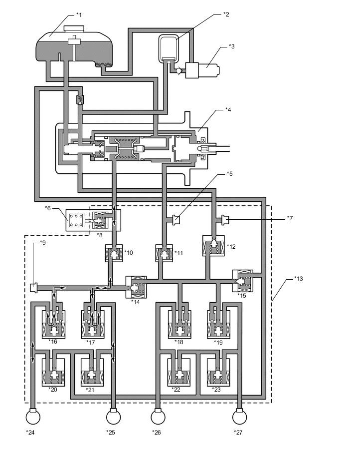
*1 Reservoir Tank *2 Accumulator *3 Pump Motor *4 Hydraulic Brake Booster *5 Master Cylinder Pressure Sensor *6 Stroke Simulator *7 Accumulator Pressure Sensor (Pacc) *8 Switching Solenoid Valve (SSC) *9 Front Wheel Cylinder Pressure Sensor *10 Switching Solenoid Valve (SMC) *11 Switching Solenoid Valve (SRC) *12 Linear Solenoid Valve (SLA) *13 Brake Actuator *14 Switching Solenoid Valve (SCC) *15 Linear Solenoid Valve (SLR) *16 Pressure Holding Solenoid Valve (FLH) *17 Pressure Holding Solenoid Valve (FRH) *18 Pressure Holding Solenoid Valve (RLH) *19 Pressure Holding Solenoid Valve (RRH) *20 Pressure Reduction Solenoid Valve (FLR) *21 Pressure Reduction Solenoid Valve (FRR) *22 Pressure Reduction Solenoid Valve (RLR) *23 Pressure Reduction Solenoid Valve (RRR) *24 Front Left Wheel Cylinder *25 Front Right Wheel Cylinder *26 Rear Left Wheel Cylinder *27 Rear Right Wheel Cylinder - - Item Power Supply Malfunction Linear Solenoid Valve SLA Off (Close) SLR Off (Close) Switching Solenoid Valve SSC Off (Close) SCC Off (Close) SMC Off (Open) SRC Off (Open) Control Solenoid Valve FLH Off (Open) FRH Off (Open) RLH Off (Open) RRH Off (Open) FLR Off (Close) FRR Off (Close) RLR Off (Close) RRR Off (Close) -
When the skid control ECU detects a malfunction of the front brake system, it closes the switching solenoid valves (SSC) and (SCC) and opens the switching solenoid valves (SMC) and (SRC). At this time, the fluid pressure generated in the regulator chamber in the hydraulic brake booster by the driver's brake pedal operation is directly supplied to the rear wheel cylinders.

*1 Reservoir Tank *2 Accumulator *3 Pump Motor *4 Hydraulic Brake Booster *5 Master Cylinder Pressure Sensor *6 Stroke Simulator *7 Accumulator Pressure Sensor (Pacc) *8 Switching Solenoid Valve (SSC) *9 Front Wheel Cylinder Pressure Sensor *10 Switching Solenoid Valve (SMC) *11 Switching Solenoid Valve (SRC) *12 Linear Solenoid Valve (SLA) *13 Brake Actuator *14 Switching Solenoid Valve (SCC) *15 Linear Solenoid Valve (SLR) *16 Pressure Holding Solenoid Valve (FLH) *17 Pressure Holding Solenoid Valve (FRH) *18 Pressure Holding Solenoid Valve (RLH) *19 Pressure Holding Solenoid Valve (RRH) *20 Pressure Reduction Solenoid Valve (FLR) *21 Pressure Reduction Solenoid Valve (FRR) *22 Pressure Reduction Solenoid Valve (RLR) *23 Pressure Reduction Solenoid Valve (RRR) *24 Front Left Wheel Cylinder *25 Front Right Wheel Cylinder *26 Rear Left Wheel Cylinder *27 Rear Right Wheel Cylinder - - Item When Front Brake Malfunction Linear Solenoid Valve SLA Off (Close) SLR Off (Close) Switching Solenoid Valve SSC Off (Close) SCC Off (Close) SMC Off (Open) SRC Off (Open) Control Solenoid Valve FLH Off (Open) FRH Off (Open) RLH Off (Open) RRH Off (Open) FLR Off (Close) FRR Off (Close) RLR Off (Close) RRR Off (Close)
-
-
Skid Control ECU
-
In the event of a malfunction the ABS, the skid control ECU can control the EBD if the EBD works properly.
-
In the event of a malfunction of the ABS and EBD, the skid control ECU illuminates the brake warning lights to alert the driver of the malfunction and prohibits the brake control system.
-
In the event of a malfunction of the TRC and/or VSC, skid control ECU prohibits the TRC and VSC operation.
-
If a communication malfunction occurs between the skid control ECU and the steering sensor, yawrate and accelerator sensors or power management control ECU, the skid control ECU stops the TRC and VSC.
-
When the power management control ECU detects the Diagnostic Trouble Code (DTC), it will disable the TRC and VSC.
-
-
-
DIAGNOSIS
-
If the skid control ECU detects a malfunction in the brake control system, then the ABS warning light, brake warning light/red (malfunction), brake warning light/yellow (minor malfunction) and slip indicator light illuminate either individually or as a group according to the function in which the malfunction has been detected, to alert the driver of the malfunction. At the same time, the skid control ECU stores Diagnostic Trouble Codes (DTCs) in memory.
-
If the skid control ECU detects a malfunction during a sensor signal check (test mode), it stores the DTCs in its memory.
-
For details of the DTCs that are stored in skid control ECU memory and the DTCs that are output through the sensor signal check functions, refer to the Repair Manual.
-