ELECTRONIC SHIFT LEVER SYSTEM
-
FUNCTION OF MAIN COMPONENTS
-
The main components of the electronic shift lever system have the following functions:
Component Function Transmission Floor Shift Assembly Shift Lever Position Sensor (Select Sensor) Detects the shift lever position (R, N, D or B), and transmits information about it (lateral movement) to the power management control ECU. Shift Lever Position Sensor (Shift Sensor) Detects the shift lever position (R, N, D or B), and transmits information about it (longitudinal movement) to the power management control ECU. P Position Switch (Transmission Shift Main Switch) As this switch turns on, it detects the driver's intention to operate the parking lock, and sends a signal to the power management control ECU. P Position Indicator Light Comes on when the parking lock is engaged, and goes off when the parking lock is disengaged. Parking Lock Actuator (Shift Control Actuator Assembly) Engages or disengages the transaxle parking lock mechanism. Power Management Control ECU Controls MG1, MG2 and the engine in accordance with each shift position, based on signals from the shift lever position sensor, P position switch (transmission shift main switch) and various ECUs. In addition, it sends a parking lock or unlock request signal to the transmission control ECU assembly. Transmission Control ECU Assembly
-
Drives the shift control actuator assembly in accordance with the parking lock or unlock request signal from the power management control ECU.
-
Receives the gearshift control lock/unlock signal from the ID code box (immobiliser code ECU), and activates/deactivates the gearshift control lock.
Certification ECU (Smart Key ECU Assembly) Verifies the ID code output from the key. ID Code Box (Immobiliser Code ECU) Compares the ID code. Combination Meter Assembly Shift Position Indicator Illuminates the shift position indicator, which the driver has selected, in accordance with the shift position signals from the power management control ECU. Buzzer Sounds to alert the driver when the reject function is activated. Master Warning Light Illuminates depending on the message displayed on the multi-information display. Multi-information Display Displays a warning message to alert the driver in accordance with a signal provided by the power management control ECU and transmission control ECU. -
-
-
SYSTEM CONTROL
-
Shift Control
-
The power management control ECU controls MG1, MG2 and the engine according to the shift state (R, N, D or B) it determined using signals from the shift lever position sensors and the switch on signal from the P position switch (transmission shift main switch). In addition, the power management control ECU sends a parking lock or unlock request signal to the transmission control ECU assembly.
-
The transmission control ECU assembly drives the shift control actuator assembly based on the parking lock or unlock request signal from the power management control ECU to engage or disengage the parking lock mechanism. In addition, it sends a park (P) position signal to the power management control ECU.
-
When the vehicle is being driven under normal conditions, any shift state can be selected, provided that the reject function has not been tripped.
-
When the power switch is turned off with the vehicle stopped, the shift state is automatically changed to park (P).
-
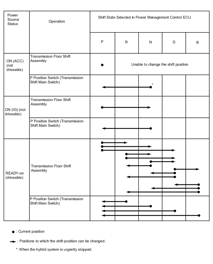
The table below shows the shift state that results from shift lever and P position switch (transmission shift main switch) operation according to the power source status.
-
-
-
FUNCTION
-
Reject Function
-
To ensure safety, this system might not change the shift state even if the driver operates the shift lever or P position switch (transmission shift main switch). In that case, it sounds a reject buzzer and changes the shift state as shown in the following table.
Shift Operation which Causes Reject Function to Operate Shift Position After Rejection Without depressing the brake pedal and with park (P) selected, the driver moves the shift lever to select another shift state. Held in park (P) While driving, the driver pushes the P position switch (transmission shift main switch). Changed to neutral (N) While driving, the driver moves the shift lever to R when drive (D) was previously selected, or to D when reverse (R) was previously selected. Changed to neutral (N) The driver moves the shift lever to B when park (P) was previously selected. Held in park (P) The driver moves the shift lever to B when reverse (R) was previously selected. Changed to neutral (N) The driver moves the shift lever to B when neutral (N) was previously selected. Held in neutral (N)
-
-
Shift Position Indicator
-
The transmission floor shift assembly is designed to always return to its home position. Therefore, the shift state that is currently selected can be checked on the shift position indicator, which is provided in the combination meter assembly.
-
In this system, engine braking is provided when brake (B) is selected. Therefore, changing to brake (B) from a state other than drive (D) is prohibited. Accordingly, if a state other than drive (D) or brake (B) has been selected, the B indicator will turn off to help prevent the driver from inadvertently moving the shift lever to B.
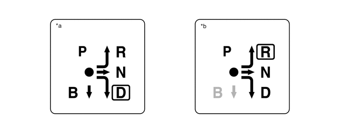
*a Displayed when drive (D) has been selected. *b Displayed when reverse (R) has been selected.
-
-
-
FAIL-SAFE
-
If the transmission control ECU detects a malfunction in the system, the transmission control ECU controls the system according to the data already stored in memory. For details, refer to the Repair Manual.
-
-
DIAGNOSIS
-
If the transmission control ECU detects a malfunction in the electronic shift lever system, the transmission control ECU blinks the P position indicator light, illuminates the master warning light and displays a message "P LOCK MALFUNCTION WHEN PARKING, PARK IN FLAT PLACE AND APPLY PARKING BRAKE SECURELY" on the multi-information display to inform the driver. If the power management control ECU detects a malfunction in the electronic shift lever system, it also illuminates the master warning light and displays the message "CHECK HYBRID SYSTEM" on the multi-information display.
-
When the transmission control ECU or power management control ECU detects a malfunction in the electronic shift lever system, the transmission control ECU or power management control ECU performs a diagnosis and memorizes the failed section. At the same time, the Diagnostic Trouble Code (DTC) is stored in its memory.
-
The DTC can be read by connecting the Global Tech Stream (GTS) to the DLC3. For details, refer to the Repair Manual.
-