BRAKE CONTROL SYSTEM
-
CONSTRUCTION
-
The hydraulic brake booster consists of the operating rod which is directly connected to the brake pedal, power piston, master cylinder piston, regulator piston and the spool valve to switch the brake fluid passage.
-
The operating rod is directly connected to the power piston, by which the operating force of the brake pedal is transmitted.
-
The regulator piston is directly connected to the spool valve, and through which the master cylinder pressure is applied to the regulator piston in the advance direction (left direction in the illustration) and the pressure boosted by the brake booster is applied to the piston in the retard direction (right direction in the illustration), thus balancing the pressures in both directions. In addition, a return spring is placed in the regulator piston to ensure the return force of the spool valve when no pressure is applied.
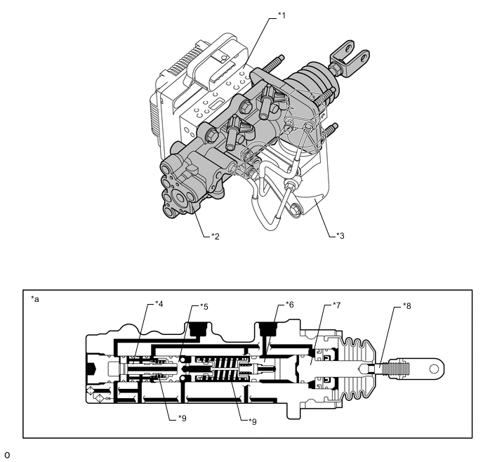
*1 Brake Actuator *2 Hydraulic Brake Booster *3 Stroke Simulator *4 Spool Valve *5 Regulator Piston *6 Master Cylinder Piston *7 Power Piston *8 Operating Rod *9 Return Spring - - *a Hydraulic Brake Booster Cross Section - - 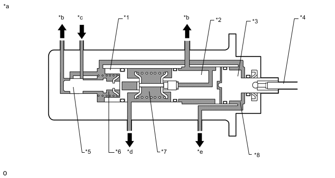
*1 Regulator Piston *2 Master Cylinder Piston *3 Power Piston *4 Operating Rod *5 Spool Valve *6 Regulator Chamber *7 Master Cylinder Chamber *8 Booster Chamber *a Simplified Diagram *b To Reservoir Tank *c From Accumulator *d To Front Brake *e To Rear Brake - -
-