HYBRID TRANSAXLE SYSTEM
-
OPERATION
-
Motive Force Transmission Path
-
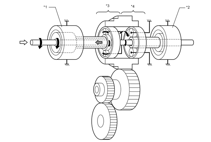
The motive force created by the engine and MG2 is transmitted by the counter drive gear of the compound gear unit, the counter driven gear, the final drive gear, and then the differential gear unit, in order to drive the front wheels.
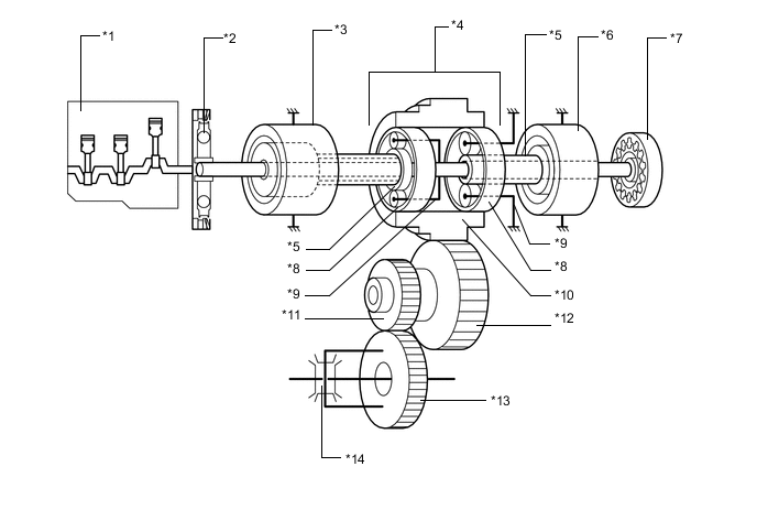
*1 Engine *2 Transmission Input Damper Assembly *3 MG1 *4 Compound Gear Unit *5 Sun Gear *6 MG2 *7 Oil Pump *8 Ring Gear *9 Carrier *10 Counter Drive Gear (Compound Gear) *11 Final Drive Gear *12 Counter Driven Gear *13 Final Driven Gear *14 Differential Gear Unit
-
-
Engine Motive Force and MG2 Motive Force Transmission Path
-
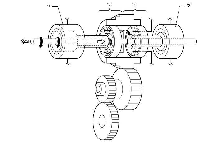
The engine motive force, which is input by the carrier, is transmitted to the ring gear. The motive force of MG2 is transmitted to the ring gear via the motor speed reduction planetary gear unit. The sum of these two motive forces is transmitted by the compound gear in order to drive the wheels.
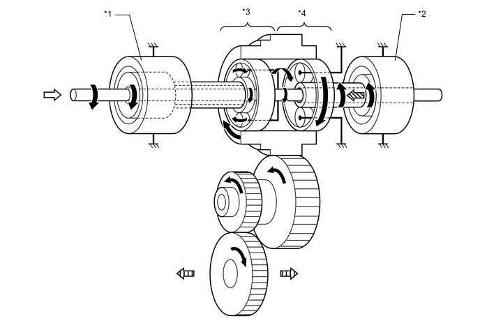
*1 MG1 *2 MG2 *3 Power Split Planetary Gear Unit *4 Motor Speed Reduction Planetary Gear Unit 
Rotation Direction 
from Engine 
from MG2 
to Wheel
-
-
MG2 Motive Force Transmission Path
-
The motive force of MG2 is transmitted via the sun gear and is transmitted to the ring gear, in order to drive the wheels. The carrier of the motor speed reduction planetary gear unit is fixed. As a result, the motor speed reduction planetary gear unit reduces the speed of MG2, increasing torque, in accordance with a set gear ratio. The rotation directions of forward and reverse becomes the opposite direction.
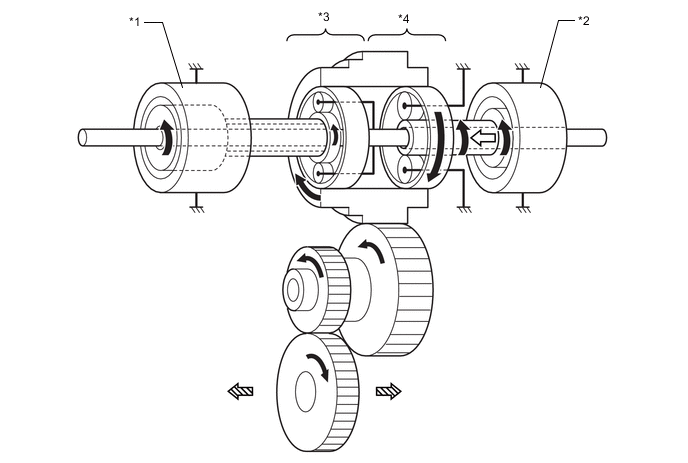
*1 MG1 *2 MG2 *3 Power Split Planetary Gear Unit *4 Motor Speed Reduction Planetary Gear Unit Rotation Direction from MG2 to Wheel - - 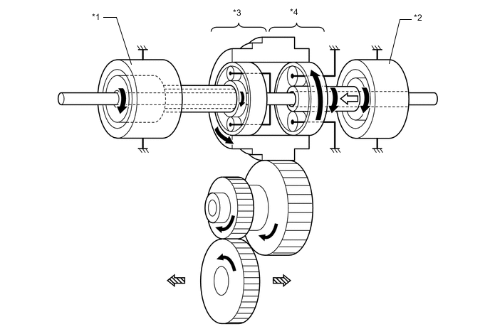
*1 MG1 *2 MG2 *3 Power Split Planetary Gear Unit *4 Motor Speed Reduction Planetary Gear Unit Rotation Direction from MG2 to Wheel - -
-
-
Engine Motive Force Transmission Path
-
The engine motive force, which is input by the carrier, is output to the sun gear. Thus, motive force is transmitted in order to operate MG1 as a generator.
*1 MG1 *2 MG2 *3 Power Split Planetary Gear Unit *4 Motor Speed Reduction Planetary Gear Unit Rotation Direction from Engine to MG1 - -
-
-
MG1 Motive Force Transmission Path
-
The motive force of MG1 is transmitted via the sun gear and is output to the carrier. Thus, motive force is transmitted in order to start the engine.
*1 MG1 *2 MG2 *3 Power Split Planetary Gear Unit *4 Motor Speed Reduction Planetary Gear Unit Rotation Direction from MG1 to Engine - -
-
-
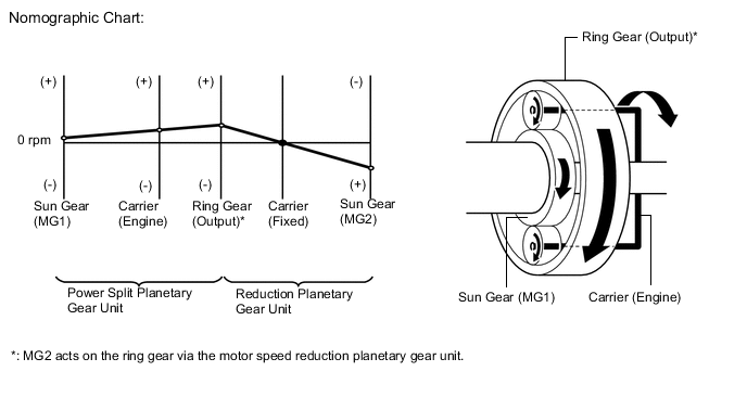
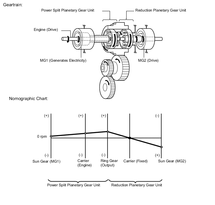
How to Read a Nomographic Chart
-
The nomographic chart below gives a visual representation of the planetary gear rotation direction, rotational speed and torque balance.
-
In the nomographic chart, a straight line is used to represent the relationship between the rotation directions and rotational speeds of the 3 gears in the planetary gear. The rotational speed of each gear is indicated by the distance from the 0 rpm point. Due to the structure of the planetary gear, the relationship between the rotational speeds of the 3 gears is always expressed by a straight line.
-
The nomographic charts and the illustrations of the geartrain operation for each vehicle driving condition shown on the following descriptions are examples only. The examples shown are 'snapshots', normal system operation is a constantly changing blend of conditions and system reactions to suit those conditions.
-
For the hybrid system, motor generators have different roles depending on the situation. Understanding the relationship between the rotation direction and torque can help to make the role of a motor generator easier to understand.
-
The table below shows the relationship of drive and electric generation for different combinations of plus or minus torque and forward or reverse rotation.
Rotation Direction Torque Condition Role of Component Forward (+) Rotation Plus Torque Drive Minus Torque Electric Generation Reverse (-) Rotation Plus Torque Electric Generation Minus Torque Drive -
As an example, if a motor generator is rotating in the forward (+) direction, and it applies minus torque, it will generate electricity (producing electrical power).
-
Alternately, if the motor generator is rotating in the reverse (-) direction and it applies minus torque, it will act as a drive source (consuming electrical power).
-
-
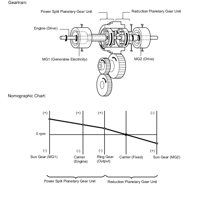
Driving Condition B: Starting Off
-
When the vehicle starts off under normal conditions, it runs using the motive force of MG2. While running under this condition, the rotational speed of the carrier (engine) is 0 rpm due to the engine being stopped. In addition, since MG1 does not generate any torque, no torque acts on the sun gear (MG1). However, the sun gear rotates freely in the (-) direction balancing the rotating ring gear.

-
-
Driving Condition C: Constant-speed Cruising
-
The torque from the engine acts on the carrier (engine) in the (+) direction, causing the sun gear (MG1) to turn in the (+) direction due to the reaction of the minus torque. MG1 generates electricity by harnessing the minus torque that acts on the sun gear (MG1).
-
-
Driving Condition D: During Full Throttle Acceleration
-
When more engine power is required, in order to increase the engine speed, the rotational speeds of the related gears change as follows. The torque from the engine acts on the carrier (engine) in the (+) direction, causing the sun gear (MG1) to turn in the (+) direction due to the reaction of the minus torque. MG1 generates electricity by harnessing the minus torque that acts on the sun gear (MG1).
-
-
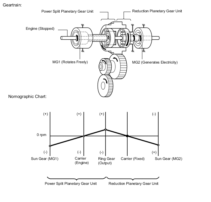
Driving Condition E: During Deceleration
-
During deceleration, the ring gear is rotated by the wheels. Under this condition, due to the engine being stopped, the rotational speed of the carrier (engine) is 0 rpm. In addition, since MG1 does not generate any torque, no torque acts on the sun gear (MG1). However, the sun gear (MG1) rotates freely in the (-) direction, balancing the rotating ring gear.
-
-
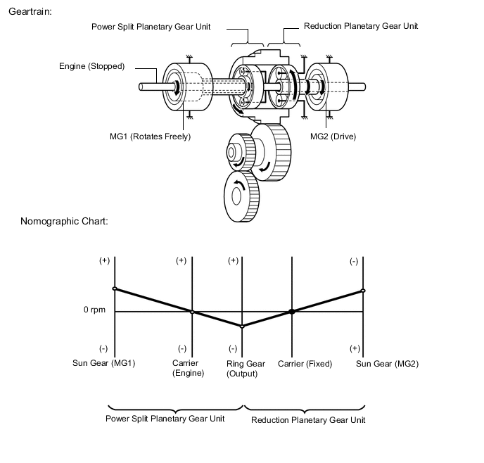
Driving Condition F: During Reverse
-
The conditions of the planetary gear are opposite to those described in "Starting Off". Due to the engine being stopped, the rotational speed of the carrier (engine) is 0 rpm but the sun gear (MG1) rotates freely in the (+) direction, balancing the rotating ring gear.
-
-