HYBRID BATTERY SYSTEM
-
CONSTRUCTION
-
The HV battery assembly mainly consists of the HV battery (Battery Modules), HV battery temperature sensor, HV battery intake air temperature sensor, hybrid battery junction block assembly, battery cooling blower assembly, battery smart unit (battery voltage sensor) and service plug grip.
-
The HV battery uses plastic container type cells. As a result, high power density, lightweight construction, and longevity have been accomplished at high levels.
-
The battery cooling blower assembly is used as a dedicated cooling system to ensure that the HV battery performs properly, despite it generating significant heat during the repetitive charge and discharge cycles.
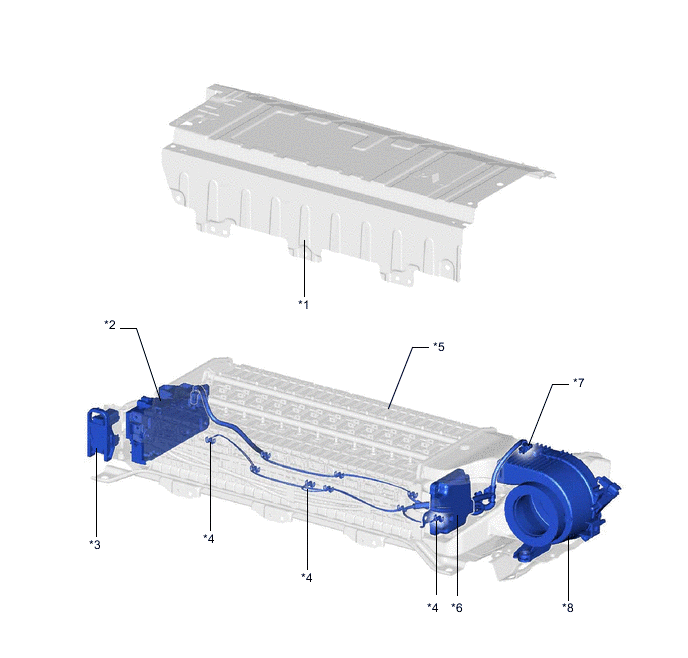
*1 HV Battery Upper Cover *2 Hybrid Battery Junction Block Assembly *3 Service Plug Grip *4 HV Battery Temperature Sensor *5 HV Battery (Battery Modules) *6 Battery Smart Unit (Battery Voltage Sensor) *7 HV Battery Intake Air Temperature Sensor *8 Battery Cooling Blower Assembly -
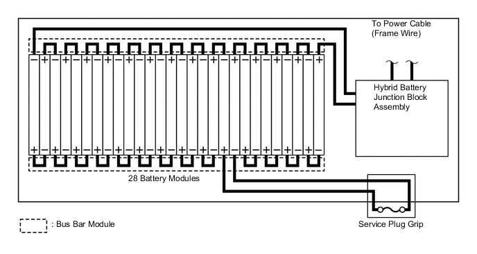
The HV battery consists of 28 separate battery modules. They are connected to each other in series through 2 bus bar modules.
-
These battery modules are each made up of 6 cells. The HV battery has a total of 168 cells (6 cells x 28 modules) and a nominal voltage of 201.6 V (1.2 V x 168 cells).
-
HV Battery Temperature Sensor and HV Battery Intake Air Temperature Sensor
-
There are 3 HV battery temperature sensors and 1 HV battery intake air temperature sensor.
-
The power management control ECU optimally controls the cooling system so that the HV battery temperature can be within a specified range according to the temperature information that is received via the battery smart unit (battery voltage sensor).
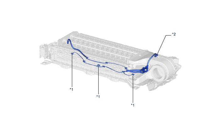
*1 HV Battery Temperature Sensor *2 HV Battery Intake Air Temperature Sensor
-
-