HYBRID CONTROL SYSTEM
-
OPERATION
-
Operation of Hybrid Vehicle
-
The hybrid system uses motive force provided by the engine and MG2, and uses MG1 as a generator. The system optimally combines these forces in accordance with various driving conditions.
-
The hybrid vehicle control ECU assembly constantly monitors the engine coolant temperature, SOC, HV battery temperature and electrical load conditions. If any of the monitoring conditions fail to satisfy the requirements, the power switch is on (READY) and the shift position is any position other than N, the hybrid vehicle control ECU assembly starts the engine.
-
The hybrid system drives the vehicle by optimally combining the operation of the engine, MG1 and MG2 in accordance with the driving conditions listed below. The vehicle conditions listed below are examples of typical vehicle driving conditions.
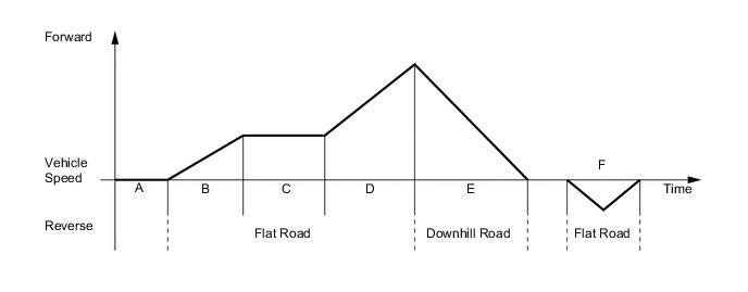
Driving Condition A Power switch on (READY) B Starting Off C Constant-speed Cruising D During Full Throttle Acceleration E During Deceleration F During Reverse
-
-
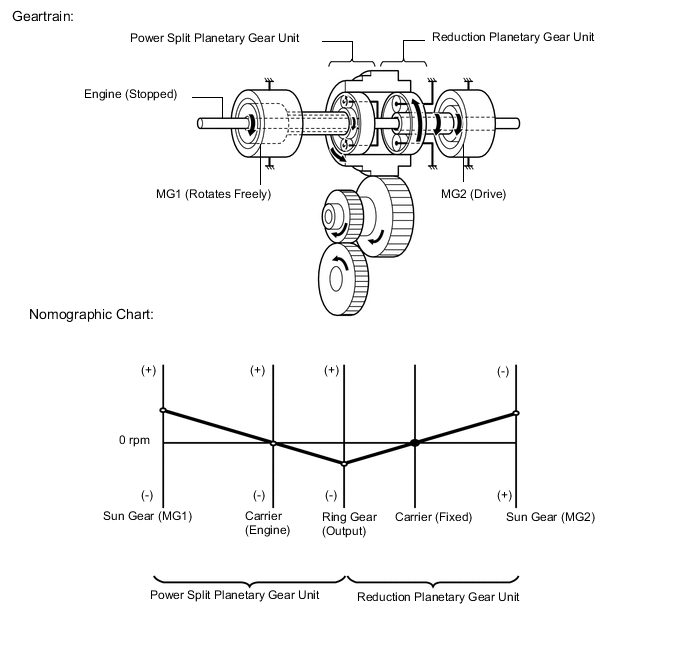
How to Read a Nomographic Chart
-
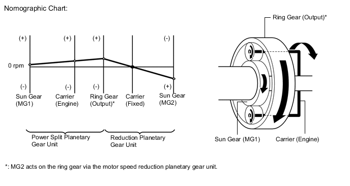
The nomographic chart below gives a visual representation of the planetary gear rotation direction, rotational speed and torque balance.
-
In the nomographic chart, a straight line is used to represent the relationship between the rotation directions and rotational speeds of the 3 gears in the planetary gear unit. The rotational speed of each gear is indicated by the distance from the 0 rpm point. Due to the structure of the planetary gear unit, the relationship between the rotational speeds of the 3 gears is always expressed by a straight line.
-
The nomographic charts and the illustrations of the geartrain operation for each vehicle driving condition shown on the following descriptions are examples only. The examples shown are 'snapshots', normal system operation is a constantly changing blend of conditions and system reactions to suit those conditions.
-
For the hybrid system, motor generators have different roles depending on the situation. Understanding the relationship between the rotation direction and torque can help to make the role of a motor generator easier to understand.
-
The table below shows the relationship of drive and electric generation for different combinations of positive or negative torque and forward or reverse rotation.
Rotation Direction Torque Condition Role of Component Forward (+) Rotation Positive Torque Drive Negative Torque Electric Generation Reverse (-) Rotation Positive Torque Electric Generation Negative Torque Drive -
As an example, if a motor generator is rotating in the forward (+) direction, and it applies negative torque, it will generate electricity (producing electrical power).
-
Alternately, if the motor generator is rotating in the reverse (-) direction and it applies negative torque, it will act as a drive source (consuming electrical power).
-
-
Driving Condition B: Starting Off
-
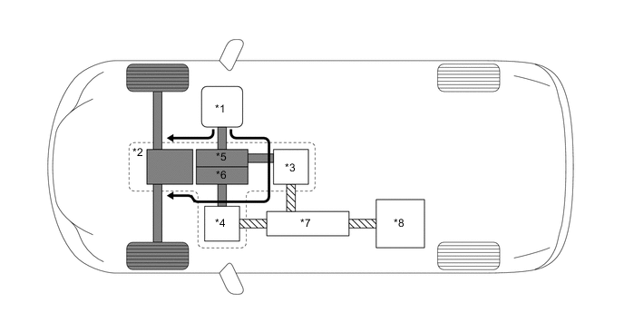
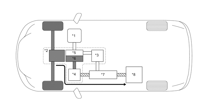
When the vehicle is started off, the vehicle operates powered by MG2. If the required drive torque increases when running with MG2 only, MG1 is activated to start the engine.
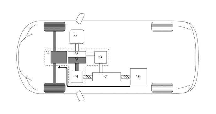
*1 Engine (Stopped) *2 Hybrid Vehicle Transaxle Assembly *3 MG1 (Rotates Freely) *4 MG2 (Drive) *5 Power Split Planetary Gear Unit *6 Motor Speed Reduction Planetary Gear Unit *7 Inverter with Converter Assembly *8 HV Battery 
Mechanical Power Path 
Electrical Power Path 
Power Transmission - - -
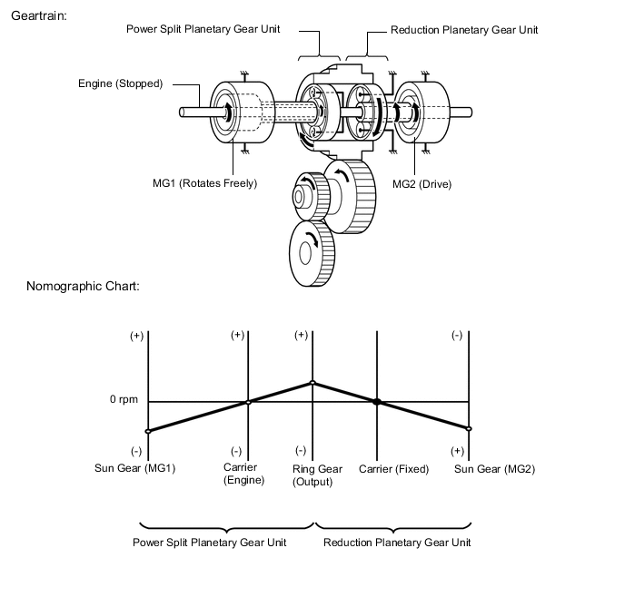
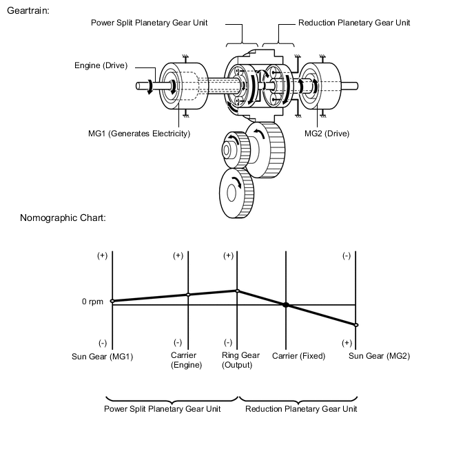
When the vehicle starts off under normal conditions, it runs using the motive force of MG2. While running under this condition, the rotational speed of the carrier (engine) is 0 rpm due to the engine being stopped. In addition, since MG1 does not generate any torque, no torque acts on the sun gear (MG1). However, the sun gear rotates freely in the (-) direction balancing the rotating ring gear.
-
-
Driving Condition C: Constant-speed Cruising
-
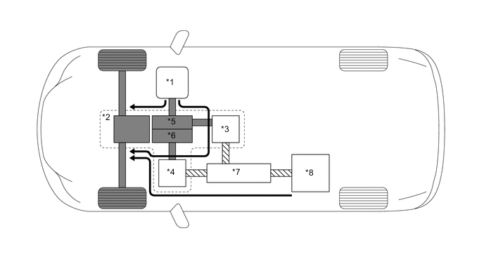
When the vehicle is running under low load and constant-speed cruising, the motive force of the engine is transmitted by the power split planetary gear unit. Some of this motive force is output directly, and the remaining motive force is used for generating electricity through MG1. Through the use of the electrical power path of an inverter, this electrical power is transmitted to MG2 to be output as the motive force of MG2. If the SOC level of the HV battery is low, it is charged by MG1 driven by the engine.
*1 Engine (Drive) *2 Hybrid Vehicle Transaxle Assembly *3 MG1 (Generates Electricity) *4 MG2 (Drive) *5 Power Split Planetary Gear Unit *6 Motor Speed Reduction Planetary Gear Unit *7 Inverter with Converter Assembly *8 HV Battery 
Mechanical Power Path Electrical Power Path Power Transmission - - -
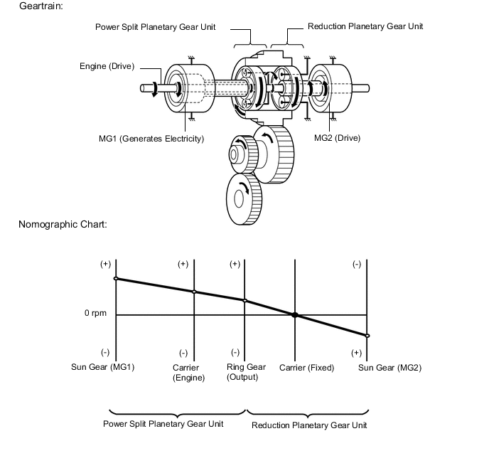
The torque from the engine acts on the carrier in the (+) direction, causing the sun gear (MG1) to turn in the (+) direction due to the reaction of the negative torque. MG1 generates electricity by harnessing the negative torque that acts on the sun gear (MG1).
-
-
Driving Condition D: During Full Throttle Acceleration
-
When the vehicle driving condition changes from low load cruising to full-throttle acceleration, the system supplements the motive force of MG2 with electrical power from the HV battery.
*1 Engine (Drive) *2 Hybrid Vehicle Transaxle Assembly *3 MG1 (Generates Electricity) *4 MG2 (Drive) *5 Power Split Planetary Gear Unit *6 Motor Speed Reduction Planetary Gear Unit *7 Inverter with Converter Assembly *8 HV Battery Mechanical Power Path Electrical Power Path Power Transmission - - -
When more engine power is required, in order to increase the engine speed, the rotational speeds of the related gears change as follows. The torque from the engine acts on the carrier in the (+) direction, causing the sun gear (MG1) to turn in the (+) direction due to the reaction of the negative torque. MG1 generates electricity by harnessing the negative torque that acts on the sun gear (MG1).
-
-
Driving Condition E: During Deceleration
-
While the vehicle decelerates with drive (D) selected, the engine is turned off and the motive force changes to zero. At this time, the wheels drive MG2, causing MG2 to operate as a generator, charging the HV battery. If the vehicle decelerates from a higher speed, the engine maintains a predetermined speed without stopping, in order to protect the planetary gears.
*1 Engine (Stopped) *2 Hybrid Vehicle Transaxle Assembly *3 MG1 (Rotates Freely) *4 MG2 (Generates Electricity) *5 Power Split Planetary Gear Unit *6 Motor Speed Reduction Planetary Gear Unit *7 Inverter with Converter Assembly *8 HV Battery Mechanical Power Path Electrical Power Path Mechanical Power Path - - -
During deceleration, the ring gear is rotated by the wheels. Under this condition, due to the engine being stopped, the rotational speed of the carrier (engine) is 0 rpm. In addition, since MG1 does not generate any torque, no torque acts on the sun gear (MG1). However, the sun gear (MG1) rotates freely in the (-) direction, balancing the rotating ring gear.

-
-
Driving Condition F: During Reverse
-
When the vehicle is being driven in reverse, the required power is supplied by MG2. At this time, MG2 rotates in the opposite direction, the engine remains stopped, and MG1 rotates in the normal direction without generating electricity.
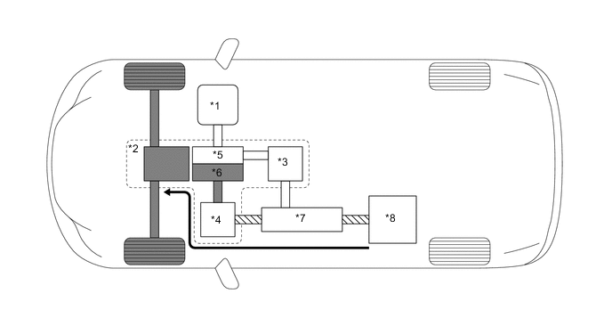
*1 Engine (Stopped) *2 Hybrid Vehicle Transaxle Assembly *3 MG1 (Rotates Freely) *4 MG2 (Drive) *5 Power Split Planetary Gear Unit *6 Motor Speed Reduction Planetary Gear Unit *7 Inverter with Converter Assembly *8 HV Battery Mechanical Power Path Electrical Power Path Power Transmission - - -
The conditions of the planetary gear units are opposite to those described in "Starting Off". Due to the engine being stopped, the rotational speed of the carrier (engine) is 0 rpm but the sun gear (MG1) rotates freely in the (+) direction, balancing the rotating ring gear.
-
-