HYBRID CONTROL SYSTEM
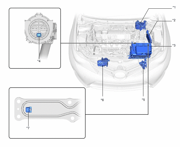
| *1 | Brake Booster with Master Cylinder Assembly - Skid Control ECU |
*2 | ECM |
| *3 | Inverter with Converter Assembly - MG ECU - Boost Converter - DC-DC Converter - Inverter |
*4 | Interlock Switch (For Power Cable Connector) |
| *5 | Inverter Water Pump Assembly | *6 | Compressor with Motor Assembly |
| *7 | Interlock Switch (For Inverter Terminal Cover) | - | - |
Figure 1. Hatchback Models
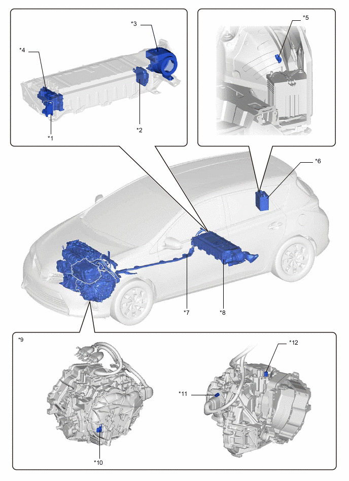
| *1 | Service Plug Grip | *2 | Battery Smart Unit (Battery Voltage Sensor) |
| *3 | Battery Cooling Blower Assembly | *4 | Hybrid Battery Junction Block Assembly - Battery Current Sensor - SMRB - SMRP - SMRG - Precharge Resistor |
| *5 | Auxiliary Battery Temperature Sensor (Thermistor Assembly) | *6 | Auxiliary Battery |
| *7 | Power Cable (Frame Wire) | *8 | HV Battery Assembly |
| *9 | Hybrid Vehicle Transaxle Assembly - Motor Generator No. 1 (MG1) - Motor Generator No. 2 (MG2) |
*10 | Motor Resolver (For MG2) |
| *11 | Motor Temperature Sensor (For MG2) | *12 | Generator Resolver (For MG1) Generator Temperature Sensor (For MG1) |
Figure 2. Wagon Models
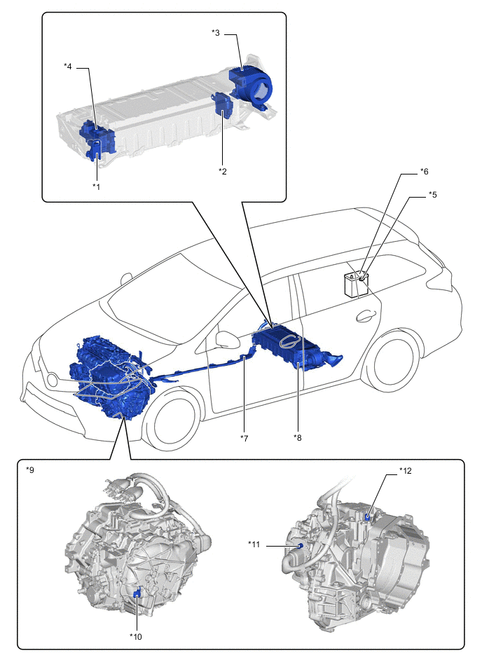
| *1 | Service Plug Grip | *2 | Battery Smart Unit (Battery Voltage Sensor) |
| *3 | Battery Cooling Blower Assembly | *4 | Hybrid Battery Junction Block Assembly - Battery Current Sensor - SMRB - SMRP - SMRG - Precharge Resistor |
| *5 | Auxiliary Battery Temperature Sensor (Thermistor Assembly) | *6 | Auxiliary Battery |
| *7 | Power Cable (Frame Wire) | *8 | HV Battery Assembly |
| *9 | Hybrid Vehicle Transaxle Assembly - Motor Generator No. 1 (MG1) - Motor Generator No. 2 (MG2) |
*10 | Motor Resolver (For MG2) |
| *11 | Motor Temperature Sensor (For MG2) | *12 | Generator Resolver (For MG1) Generator Temperature Sensor (For MG1) |
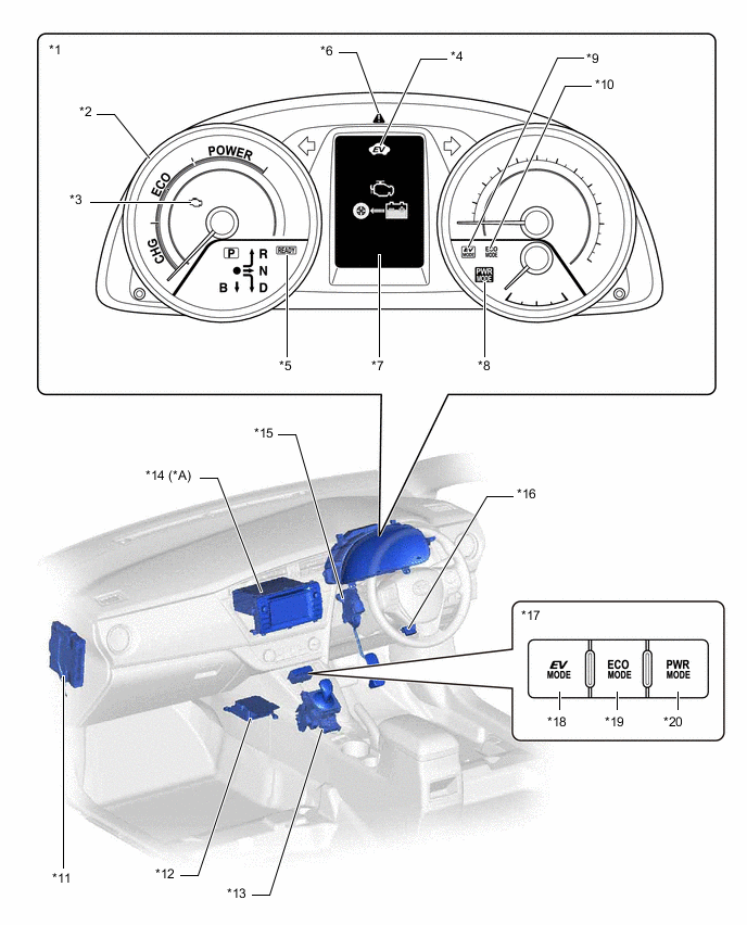
Figure 3. LHD Models
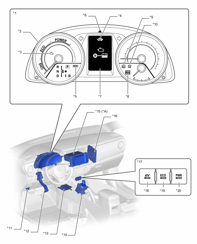
| *A | Models with Touch Screen System or Display Audio System | - | - |
| *1 | Combination Meter Assembly | *2 | Hybrid System Indicator |
| *3 | Malfunction Indicator Lamp (MIL) | *4 | EV Drive Indicator Light |
| *5 | READY Indicator Light | *6 | Master Warning Light |
| *7 | Multi-information Display - Energy Monitor |
*8 | Power Mode Indicator Light |
| *9 | EV Mode Indicator Light | *10 | ECO Mode Indicator Light |
| *11 | DLC3 | *12 | Accelerator Pedal Sensor Assembly |
| *13 | Airbag Sensor Assembly | *14 | Lower Shift Lever Assembly - Shift Lever Position Sensor (Shift Sensor) - Shift Lever Position Sensor (Select Sensor) |
| *15 | Radio and Display Receiver Assembly | *16 | Power Management Control ECU |
| *17 | Combination Switch Assembly | *18 | EV Drive Mode Switch |
| *19 | ECO Mode Switch | *20 | Power Mode Switch |
Figure 4. RHD Models
| *A | Models with Touch Screen System or Display Audio System | - | - |
| *1 | Combination Meter Assembly | *2 | Hybrid System Indicator |
| *3 | Malfunction Indicator Lamp (MIL) | *4 | EV Drive Indicator Light |
| *5 | READY Indicator Light | *6 | Master Warning Light |
| *7 | Multi-information Display - Energy Monitor |
*8 | Power Mode Indicator Light |
| *9 | EV Mode Indicator Light | *10 | ECO Mode Indicator Light |
| *11 | Power Management Control ECU | *12 | Airbag Sensor Assembly |
| *13 | Shift Control Unit Assembly - Shift Sensor - Select Sensor |
*14 | Radio and Display Receiver Assembly |
| *15 | Accelerator Pedal Sensor Assembly | *16 | DLC3 |
| *17 | Combination Switch Assembly | *18 | EV Drive Mode Switch |
| *19 | ECO Mode Switch | *20 | Power Mode Switch |