СИСТЕМА CVT
-
FUNCTION OF MAIN COMPONENTS
-
The main components of the K313 Continuously Variable Transaxle (CVT) are as follows:
Component Function Continuously Variable Transaxle Assembly On-off Solenoid Valve for Clutch (SC) Used to switch control of the linear solenoid valve for lock-up control (SLU) for forward and reverse clutch control. On-off Solenoid Valve for Lock-up (SL) Used to switch control of the linear solenoid valve for lock-up control (SLU) during lock-up clutch control. Linear Solenoid Valve for Lock-up Control (SLU) Performs forward and reverse clutch control or lock-up clutch control depending on the state of the on-off solenoid valve for clutch (SC) and on-off solenoid valve for lock-up (SL). Linear Solenoid Valve for Primary Pulley Control (SLP) Controls the oil pressure of the primary pulley in accordance with the vehicle speed and accelerator pedal position signals to control the speed ratio. Linear Solenoid Valve for Secondary Pulley Control (SLS) Controls the oil pressure of the secondary pulley in accordance with the input shaft torque to control belt clamping force. Transmission Revolution Sensor (NIN) Detects the primary pulley speed (input speed). Transmission Revolution Sensor (NOUT) Detects the secondary pulley speed (output speed). Transmission Revolution Sensor (NT) Detects the turbine speed of the torque converter. CVT Fluid Temperature Sensor (Transmission Wire) Detects the CVT fluid temperature. Oil Pressure Sensor Detects the steel belt clamping force. Engine Coolant Temperature Sensor Detects the engine coolant temperature. Throttle Body Assembly Throttle Position Sensor Detects the opening angle of the throttle valve. Airbag ECU Assembly Yawrate Sensor Detects the vehicle's longitudinal and lateral acceleration and deceleration. Acceleration Sensor Stop Light Switch Assembly Detects when the brake pedal is depressed. Park/Neutral Position Switch Assembly Detects the shift lever position. Transmission Floor Shift Assembly Transmission Control Switch
-
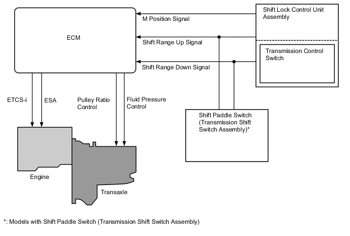
Detects when the shift lever is in M.
-
Detects the driver's shift-up and shift-down operations when the shift lever is in M.
Shift Paddle Switch (Transmission Shift Switch Assembly)*
-
Detects the driver's shift-up and shift-down operations in 7-speed sport sequential shiftmatic mode.
-
Operating this switch when the shift lever is in D changes the mode temporarily to 7-speed sport sequential shiftmatic mode.
Crank Position Sensor Detects the engine speed. Accelerator Pedal Sensor Detects the accelerator pedal opening angle. Brake Actuator Assembly Skid Control ECU
-
Transmits the vehicle speed and the longitudinal acceleration signal to the ECM.
-
Transmits the operating states of the ABS to the ECM.
Air Conditioning Amplifier Assembly Transmits the operating state of the air conditioning system to the ECM. ECM Drives each solenoid valve based on signals from each sensor and switch and optimally controls the CVT. Combination Meter Assembly Transmits the vehicle speed signal to the ECM. Combination Meter Assembly Shift Position and Shift Range Indicator Indicates the shift lever position. Malfunction Indicator Lamp (MIL) Illuminates to inform the driver when the ECM detects a malfunction. SPORT Mode Indicator Illuminates when SPORT mode is on. Buzzer Sounds when shift-down operation is rejected in 7-speed sport sequential shiftmatic mode. SPORT Mode Switch (Pattern Select Switch Assembly) Operating this switch turns SPORT mode on or off. *: Models with shift paddle switch (transmission shift switch assembly)
-
-
-
SYSTEM CONTROL
-
Control List
-
The electronic control system of the K313 CVT consists of the controls listed below.
Control Outline Engine-CVT Integrated Control Effects coordinated control of the CVT system and engine control system to ensure both smooth and powerful driving that excels in shift response and fuel economy. Automatic Shift Control (Speed Ratio Control) Controls the primary pulley speed to approach the calculated target input rotation speed based on information such as the accelerator pedal opening angle, vehicle speed and brake signals. Acceleration Improvement Control Keeps the acceleration for the accelerator pedal opening angle to a certain level, improving the linearly acceleration feeling and expanding feeling for driver's accelerator pedal operation. Deceleration Improvement Control During deceleration, a pulley ratio which allows high engine speed to be maintained, is calculated, thus ensuring adequate engine braking. G AI-shift Control Helps to ensure the vehicle proper posture when entering a corner and ensures the driving torque when exiting a corner. Uphill/Downhill Shift Control Controls to restrict upshifts or to provide appropriate engine braking force by using the ECM to determine whether the vehicle is traveling on uphill or downhill. Lock-up Control The ECM sends a current to the on-off solenoid valve for clutch (SC) and on-off solenoid valve for lock-up (SL), and linear solenoid valve for lock-up control (SLU) based on the throttle position sensor signal and vehicle speed signal, and engages or disengages the lock-up clutch. Flex Lock-up Control Neutral Control When the vehicle speed is approximately 10 km/h (6 mph) or less during braking or the vehicle isstopped, the driving force to the transaxle is shut off to improve fuel economy. 7-speed Sport Sequential Shiftmatic Mode Enables driving in a gear step selected using the shift lever, providing engine braking force appropriate to each gear step.
-
-
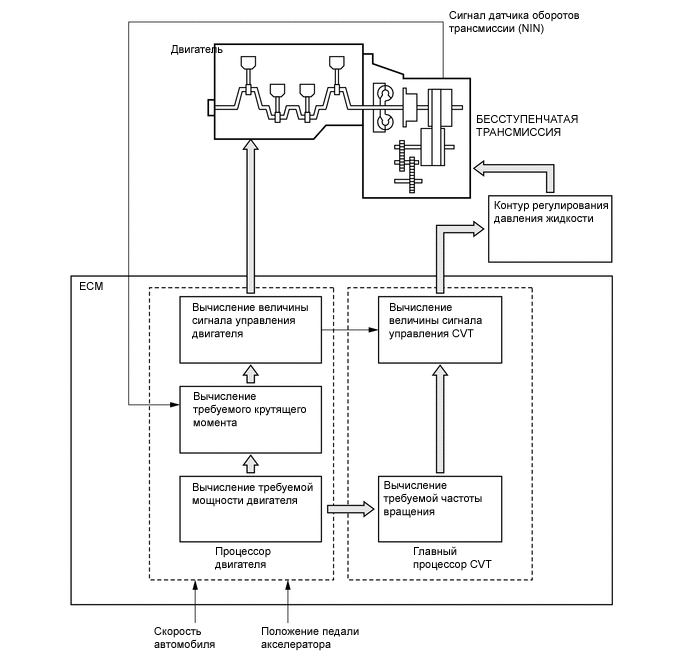
Engine-CVT Integrated Control
-
To effect fine-tuned control in accordance with driving conditions, various signals are exchanged between the engine control system and the CVT system. As a result, both smooth and powerful driving that excels in shift response and fuel economy has been achieved.
-
-
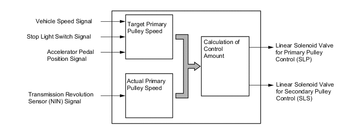
Automatic Shift Control (Speed Ratio Control)
-
The ECM calculates the target primary pulley speed in accordance with the accelerator pedal position signal, vehicle speed signal, and stop light switch signal, in order to attain an optimal pulley ratio and shifting speed. To adjust the actual primary pulley (acquired from the primary speed sensor) to match the target primary pulley speed, the ECM actuates linear solenoid valve for primary pulley control (SLP) and linear solenoid valve for secondary pulley control (SLS) in order to control the pressure of primary pulley and secondary pulley. As a result, the optimal pulley ratio and shifting speed are achieved.
-
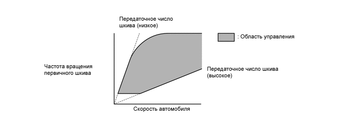
When the shift lever is in D, the system effects engine integrated control to optimize fuel economy characteristics and driving performance.
-
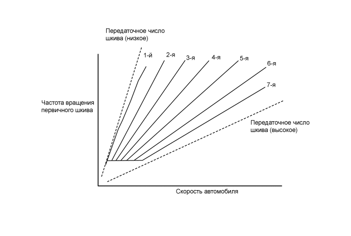
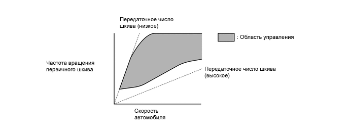
When the shift lever is in M, the shift characteristic is as shown below. The system will upshift automatically when the vehicle reaches the set speed during acceleration.
-
SPORT mode restricts the variable range of the high gear ratio to ensure a more direct feeling, and provides Deceleration Improvement Control and G AI-shift Control to support vehicle stability during cornering and to ensure responsiveness when exiting a corner by holding the optimal gear ratio. In addition, newly adopted Step Shift Control provides excellent response and linear and powerful acceleration and when driving on winding roads or situations in which gentle acceleration is required.
Tech Tips
-
SPORT mode is turned on by pressing the SPORT mode switch (pattern select switch assembly).
-
When SPORT mode is selected, the SPORT mode indicator in the combination meter assembly illuminates.
-
When SPORT mode is operating, SPORT mode is turned off by pressing the SPORT mode switch (pattern select switch assembly).
-
When the engine is stopped with SPORT mode on, SPORT mode is turned off.
-
When the shift lever is in M, or temporary 7-speed sport sequential shiftmatic mode is selected with the shift lever in D*, the gear ratio for each gear step is maintained.
*: Models with shift paddle switch (transmission shift switch assembly)
-
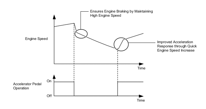
Low gear ratio shift schedule
-
The variable range of the low gear ratio is restricted to ensure appropriate engine braking force when decelerating and to enhance engine response when accelerating.
-
Depending on the accelerator pedal depression amount, the engine can quickly rev toand be maintained in the high speed range, ensuring quick acceleration andresponsiveness.
-
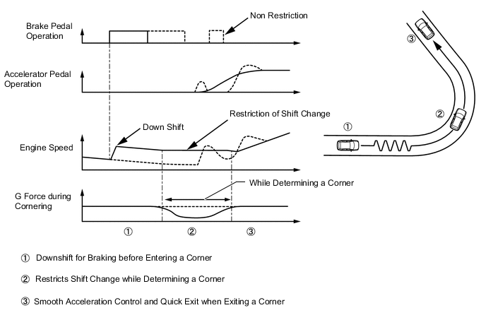
G AI-shift control
-
G AI-shift control generates an appropriate engine braking force by varying the gear ratio according to the brake pedal depression force.
-
If a certain amount of lateral G force is detected, G AI-shift control determines that the vehicle is cornering and maintains engine speed by restricting the variable gear range, ensuring excellent throttle control and appropriate driving force.
-
Step Shift Control
-
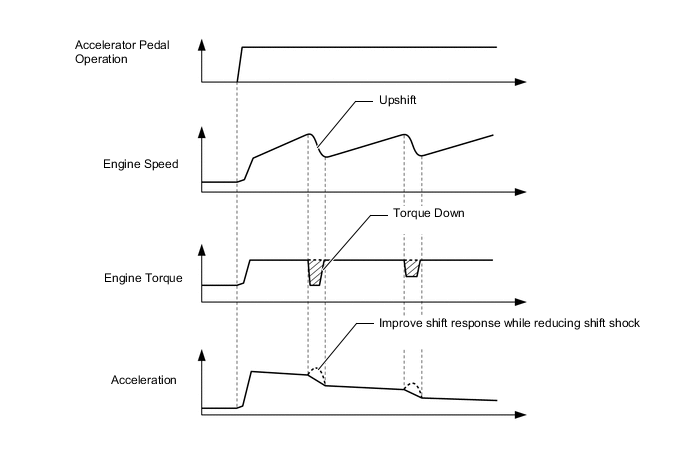
Step Upshift Control
-
During acceleration, Step Upshift Control enables the engine speed to increase in proportion to vehicle speed and repeats upshifts to promote unconstrained and powerful acceleration.
-
During upshift, the throttle valve is electronically controlled to improve shift response and reduce shift shock.
-
-
-
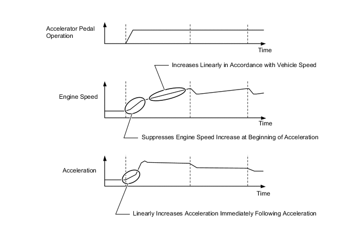
Acceleration Improvement Control
-
The system determines the driver's acceleration request based on the vehicle speed and the changes in the accelerator pedal position. When the system determines this request, it will change the shift characteristic into one in which the engine speed and vehicle speed increase linearly. This improves the acceleration feeling.
-
-
Deceleration Improvement Control
-
During deceleration, a pulley ratio which allows high engine speed to be maintained, is calculated, thus ensuring adequate engine braking.
-
During subsequent acceleration, the engine is controlled to generate driving force quickly.
-
-
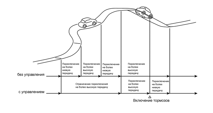
Uphill/Downhill Shift Control
-
Uphill/downhill shift control helps perform optimal shifting while driving on a winding uphill or downhill road.
-
When the ECM determines the vehicle is traveling uphill, the control restricts upshifting, thus offering smooth driving.
-
If a signal indicating that the driver has operated the brake pedal is input when the ECM has determined the vehicle is traveling downhill, the control downshifts to generate optimal engine braking force.
-
The actual acceleration calculated from the vehicle speed signal is compared with the reference acceleration (based on level road travel) stored in the ECM to determine uphill or downhill travel.
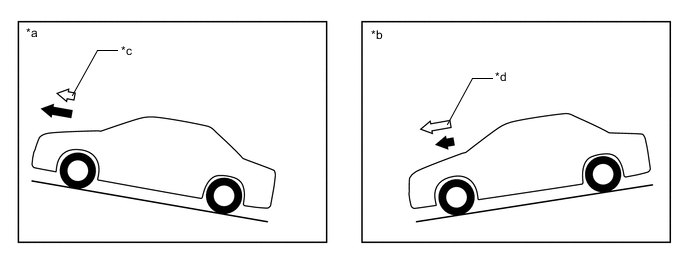
*a Uphill *b Downhill *c Smaller *d Greater 
Reference Acceleration 
Actual Acceleration
-
-
Lock-up Control
-
The lock-up operation range has been expanded from that of previous continuously variable transaxles, thus enabling control to start from low speeds.
-
The lock-up operation range during deceleration has been expanded to the low-speed range. This expands the fuel cut range and achieves excellent fuel economy.
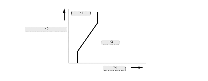
*1 Lock-up Off *2 Throttle Opening Angle *3 Lock-up On *4 Vehicle Speed
-
-
Flex Lock-up Control
-
In order to improve the transmission efficiency and also the fuel economy, the linear solenoid valve for lock-up control (SLU) for lock-up engagement pressure control is employed to deliver flex lock-up control that can provide more precise control than that of a conventional lock-up clutch mechanism.
-
The flex lock-up control consists of flex start control and flex lock-up control during deceleration.
-
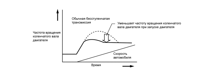
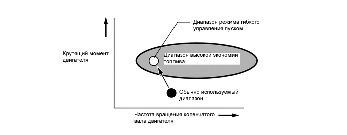
The flex start control aggressively operates the lock-up clutch during start-off to increase the transmission efficiency, as a result, the engine can run in its most efficient operating range.
-
Flex lock-up control during deceleration is used to expand the fuel-cut range. It operates the lock-up clutch over the low vehicle speed range when the vehicle decelerates so that minimal speed difference between the engine speed and turbine speed can be maintained.
-
-
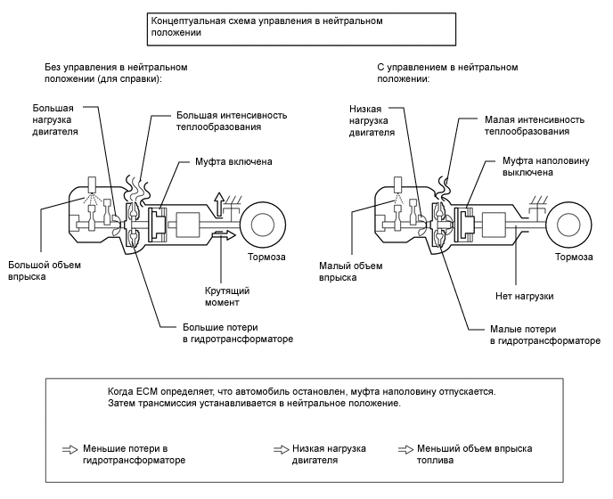
Neutral Control
-
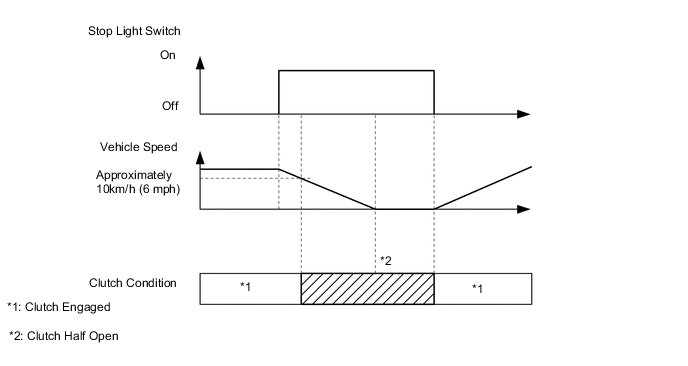
When the vehicle speed is approximately 10 km/h (6 mph) or less during braking or thevehicle is stopped with the shift lever in D, the engine and CVT are disconnected (theforward clutch is released halfway) to reduce engine load.
-
-
7-speed Sport Sequential Shiftmatic
-
The driver can select the desired gear step by moving the shift lever to "+" (forward) or "-" (backward) while the shift lever is in M (7-speed sport sequential shiftmatic mode). Thus, the driver is able to change shift range with a manual-like feel.
-
A shift paddle switch (transmission shift switch assembly), which enables the driver to perform shift operations while holding the steering wheel, is provided depending on the model.
-
7-speed sport sequential shiftmatic mode can be selected from normal driving mode by moving the shift lever to M. The driver can change the gear step by selecting it using the shift lever or shift paddle switch (transmission shift switch assembly)*1 and engine braking force is provided in accordance with the selected gear step.*2
*1: Models with shift paddle switch (transmission shift switch assembly)
*2: On models with the shift paddle switch (transmission shift switch assembly), if the shift paddle switch (transmission shift switch assembly) "+ (UP)" or "- (DOWN)" is operated during normal driving mode with the shift lever in D, gear step change operations are temporarily made available.
-
Through the engine-CVT integrated control, the pulley ratio and engine torque which correspond to various shift speeds are finely controlled, thus improving shift response and achieving reduced shifting shock.
-
The shift position and shift range indicator is provided in the multi-information display of the combination meter assembly. When the shift lever is in P, R, N or D, the shift position is indicated on the shift position and shift range indicator. When the shift lever is in M, or temporary 7-speed sport sequential shiftmatic mode is selected with the shift lever in D,* "M" or "D" and the selected shift range is displayed on the shift position and shift range indicator.
*: Models with shift paddle switch (transmission shift switch assembly)
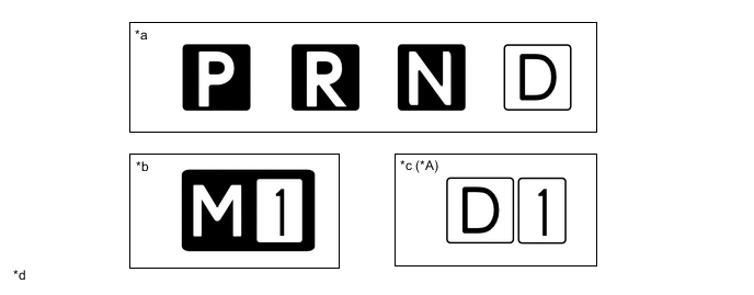
*A Models with Shift Paddle Switch (Transmission Shift Switch Assembly) - - *a When shift lever is in P, R, N or D *b When shift lever is in M *c During temporary 7-speed sport sequential shiftmatic mode with shift lever in D *d This illustration is an example only. -
In 7-speed sport sequential shiftmatic mode, the transmission automatically upshifts or downshifts under the following conditions:
Condition System Control Engine is under-revving. 1 step downshift Engine is over-revving. 1 step upshift -
When the vehicle is stopped during 7-speed sport sequential shiftmatic mode, the transmission automatically downshifts to M1.
-
The ECM will restrict the section of shift ranges step if it detects a malfunction.
-
If the vehicle speed or engine speed exceeds or goes below a preset level in response to the driver's downshift operation request, changing the shift range will be prohibited. In this case, the buzzer in the combination meter will sound to alert the driver.
-
-
-
FAIL-SAFE
-
This fail-safe function minimizes the loss of operability when an abnormality occurs in a sensor or solenoid valve. For details, refer to the Repair Manual.
-
-
DIAGNOSIS
-
When the ECM detects a malfunction, the ECM stores information related to the malfunction. Furthermore, the ECM illuminates or blinks the Malfunction Indicator Lamp (MIL) in the combination meter assembly to inform the driver.
-
The ECM will also store Diagnostic Trouble Codes (DTCs) of the malfunctions. The DTCs stored in the ECM are output to the Global TechStream (GTS) via the ECM and the DLC3. For details, refer to the Repair Manual.
Tech Tips
To clear a DTC that is stored in the ECM, use the Global TechStream (GTS) or disconnect the cable from the battery terminal for 1 minute or longer.
-