СИСТЕМА МЕХАНИЧЕСКОЙ ТРАНСМИССИИ "MULTIMODE"
-
CONSTRUCTION
-
Shift and Select Actuator Assembly
-
The shift and select actuator assembly consists of the parts listed below. This actuator cannot be disassembled.
-
2 motors (shift and select motors)
-
2 sensors (shift and select stroke sensors)
-
Shift and select mechanism (shift and select lever shaft, shift pinion gear, ring gear, shift actuator plate, select pinion gear and select actuator plate)
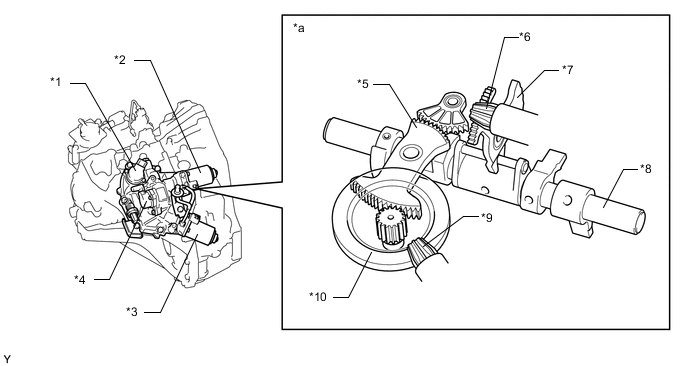
*1 Shift Stroke Sensor *2 Select Motor *3 Shift Motor *4 Select Stroke Sensor *5 Shift Actuator Plate *6 Select Pinion Gear *7 Select Actuator Plate *8 Shift and Select Lever Shaft *9 Shift Pinion Gear *10 Ring Gear *a Shift and Select Mechanism - - -
-
-
Shift Stroke Sensor and Select Stroke Sensor
-
The shift stroke sensor and select stroke sensor have the same construction and output characteristics.
-
These sensors consist of 2 Hall ICs and a magnetic yoke that rotates in unison with the shift and select lever shaft movement.
-
These sensors convert the changes in magnetic flux that are caused by the rotation of the shift motor and the select motor (hence, the rotation of the magnetic yoke) into electric signals, and output them to the TCM.
-
The TCM determines the extent of the shift stroke and the select stroke from these electric signals in order to determine the selected gear.
-
The main and sub circuits in the shift stroke and the select stroke sensors exhibit the same output characteristics.
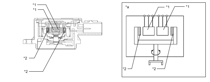
*1 Hall IC *2 Magnetic Yoke *a Example Diagram - - 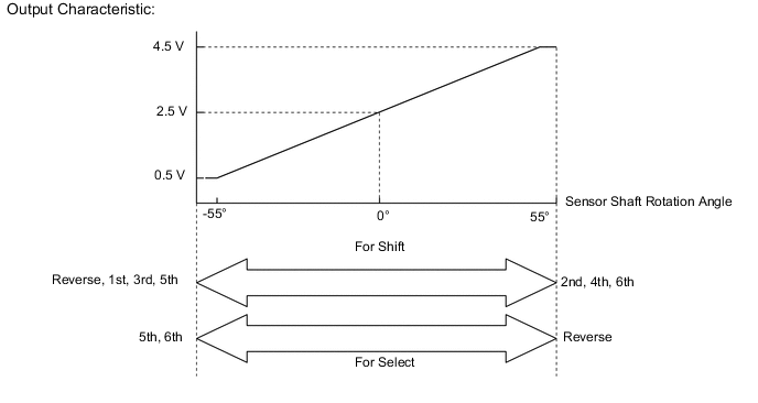
-
-
-
OPERATION
-
When the select motor is actuated, rotary movement is transmitted to the select pinion gear (see A in the illustration below). The select actuator plate moves (see B) in sync with the select pinion gear rotation to operate the shift and select lever (see C).
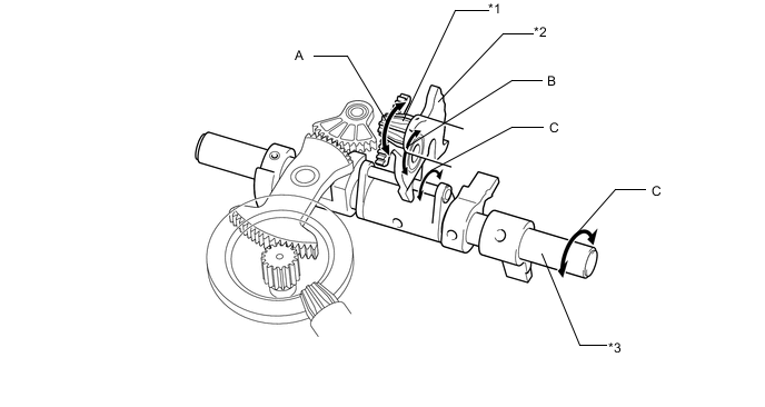
*1 Select Pinion Gear *2 Select Actuator Plate *3 Shift and Select Lever - - -
When the shift motor is actuated, rotary movement is transmitted to the shift pinion gear (see A in the illustration below). And then, the shift pinion gear rotation is transmitted to the ring gear, causing the pinion gear located at the center of the ring gear to rotate (see B). The shift actuator plate is moved by the rotary motion input from the pinion gear (see C), and then the shift and select lever operates (see D).
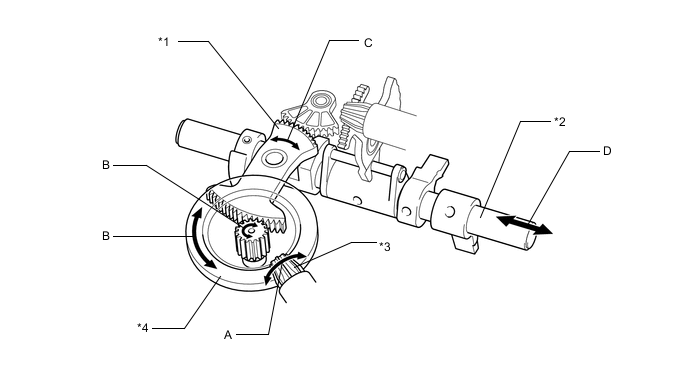
*1 Shift Actuator Plate *2 Shift and Select Lever *3 Shift Pinion Gear *4 Ring Gear -
These movements are transmitted to the shift fork shaft lever. As a result, the selected gear is changed.
-