СИСТЕМА ОХЛАЖДЕНИЯ
Figure 1. Models with Continuously Variable Transaxle
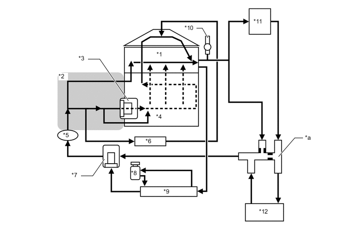
| *1 | Cylinder Head Sub-assembly | *2 | Water Inlet |
| *3 | Thermostat (Cylinder Block Side) | *4 | Cylinder Block Sub-assembly |
| *5 | Engine Water Pump Assembly | *6 | Throttle Body with Motor Assembly |
| *7 | Thermostat | *8 | Intercooler Reserve Tank Assembly |
| *9 | Radiator Assembly | *10 | Bleeder Valve (No. 7 Water By-pass Hose) |
| *11 | Heater Radiator Unit Sub-assembly | *12 | CVT Fluid Warmer (Transmission Oil Cooler) |
| *a | 5-way Mechanism | - | - |
Figure 2. Models with Manual Transaxle
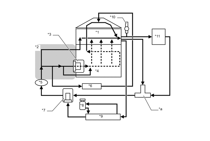
| *1 | Cylinder Head Sub-assembly | *2 | Water Inlet |
| *3 | Thermostat (Cylinder Block Side) | *4 | Cylinder Block Sub-assembly |
| *5 | Engine Water Pump Assembly | *6 | Throttle Body with Motor Assembly |
| *7 | Thermostat | *8 | Intercooler Reserve Tank Assembly |
| *9 | Radiator Assembly | *10 | Bleeder Valve (No. 7 Water By-pass Hose) |
| *11 | Heater Radiator Unit Sub-assembly | - | - |
| *a | 3-way Mechanism | - | - |