СИСТЕМА СНИЖЕНИЯ ТОКСИЧНОСТИ ОТРАБОТАВШИХ ГАЗОВ
-
FUNCTION OF MAIN COMPONENTS
-
The main components of the 1ND-TV emission control system are as follows:
Components Outline Quantity Function Differential Pressure Sensor Semiconductor Strain Gauge Type 1 This pressure sensor measures the pressure differences between the front and back of the DPF catalyst with PM in order to detect the clogging. Exhaust Gas Temperature Sensor Thermistor Type 2 The exhaust gas temperature sensor is installed in the front and back of the oxidation catalyst in order to detect the temperature of the exhaust gas. Air Fuel Ratio Sensor Wide Band Type with Heater 1 This sensor detects the oxygen concentration in the exhaust gas linearly. Oxidation Catalytic Converter (Exhaust Manifold Converter Sub-assembly) On Exhaust Manifold 1 The converter oxidizes CO and HC in the exhaust gas to purify and convert them into CO2and H2O, and has excellent pre-heating performance as it is provided on the exhaust manifold.
DPF Catalytic Converter (No. 2 Exhaust Manifold Converter Sub-assembly) On Exhaust Pipe Front 1 This converter traps PM in the exhaust gas and further oxidizes CO and HC to purify and convert them into CO2and H2O.
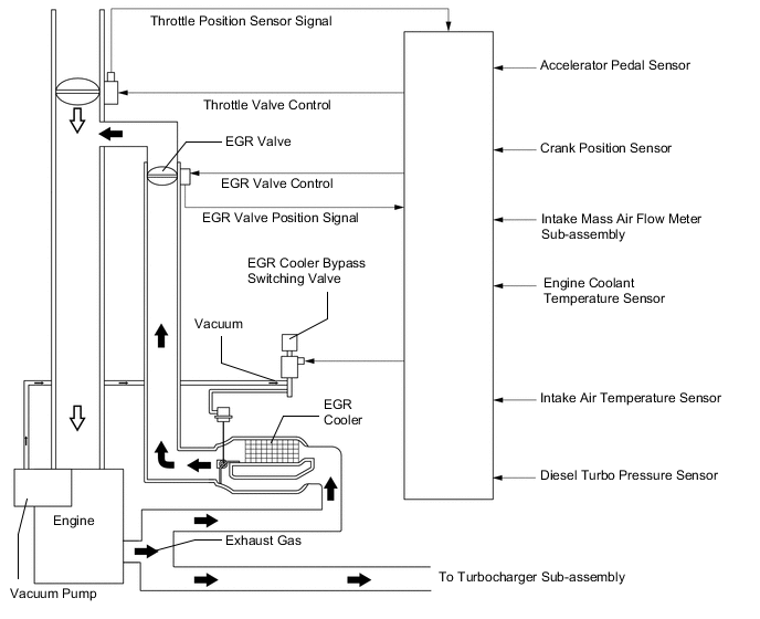
EGR Cooler Assembly Water-cooled Type 1 The EGR cooler cools the exhaust gas temperature to improve the EGR efficiency, thus reducing NOXin the exhaust gas.
EGR Cooler Bypass Switching Valve VSV Drive Type 1 This valve opens and closes to control the EGR cooler bypass amount in accordance with the engine operating conditions. EGR Valve (Electric EGR Control Valve Assembly) DC Motor Drive Type 1 This valve opens and closes in accordance with the engine operating conditions and optimally controls the EGR amount. EGR Valve Position Sensor Contact Type 1 This sensor detects the actual amount of the EGR valve opening.
-
-
SYSTEM CONTROL
-
System Control Table
-
The emission control system of the 1ND-TV engine has the following systems.
System Outline EGR Control Based on the signals received from the sensors, the ECM determines the EGR volume via the EGR valve and throttle valve in accordance with the engine condition. Catalyst Support Control Based on the signals received from the sensors, the ECM controls the fuel injection timing, injection frequency and the engine idle speed to purify PM. Air Fuel Ratio Sensor Heater Control Maintains the temperature of the air fuel ratio sensor at an appropriate level to increase accuracy of detection of the oxygen concentration in the exhaust gas.
-
-
EGR Control
-
This system is designed to reduce and control NOx formation due to a reduction of peak temperature in the engine combustion chamber, which is accomplished by introducing the exhaust gas into the intake manifold.
-
By sensing the engine driving conditions and actual amount of the EGR valve opening, the ECM operates the EGR valve and diesel throttle control motor, and regulates the amount of exhaust gas.
-
-
Catalyst Support Control
-
The ECM judges the DPF catalyst conditions, based on signals from the air flow meter, engine coolant temperature sensor, 2 exhaust gas temperature sensors, differential pressure sensor and air fuel ratio sensor to control the fuel injection timing, injection frequency and the engine idle speed for the catalyst support control.
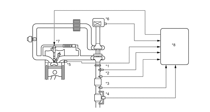
*1 Air Fuel Ratio Sensor *2 Exhaust Gas Temperature Sensor *3 No. 2 Exhaust Gas Temperature Sensor *4 Differential Pressure Sensor *5 Engine Coolant Temperature Sensor *6 Intake Mass Air Flow Meter Sub-assembly *7 Injector Assembly *8 ECM -
If the DPF catalyst temperature becomes low, catalyst performance decreases, resulting in an increase of the amount of PM stuck in the filter substrate. When the ECM detects clogs in the filter substrate by calculating the accumulated volume of PM discharged by the engine, a post injection and an idle-up control are performed to reduce PM. At the same time, filter substrate temperature becomes high and PM reacts with active oxygen and changes into CO2for purification. Fuel efficiency drops during this control.
Tech Tips
In post injection, fuel is injected into the cylinder at a timing at which the fuel is not combusted, sending the fuel into the DPF and increasing the exhaust gas temperature by catalytic oxidation reaction, resulting in increased catalyst temperature.
-
A small portion of the fuel injected by the post injection enters the crankcase via the cylinder walls, causing dilution of the engine oil. The oil level is less likely to increase during normal use, as the fuel in the oil evaporates with the increase in the engine oil temperature. However, the engine oil is gradually diluted after consecutive trips of which the running distance is short, which results in reduced lubricating performance. In an attempt to prevent this, the oil level sensor detects the engine oil level and turns on/blinks the oil change reminder indicator light to urge the driver to change the engine oil.
-
-