БЛОК ДВИГАТЕЛЯ
-
CONSTRUCTION
-
A connecting rod sub-assembly made of forged steel (C70) is used.
-
The connecting rod sub-assemblies are manufactured by drop forging and then cracked.
-
The connecting rod sub-assembly and the connecting rod bearing cap are integrally cast and the connecting rod big end bore is created.
-
In the case of a cracked connecting rod sub-assembly, the connecting rod big end bore is separated by breaking. A notch is applied with a laser at the predetermined breaking point for this purpose. Then, the connecting rod big end bore is gripped on a 2-part expanding device and separated by driving in a wedge.
-
The process of cracking (breaking) the connecting rod bearing cap creates a fine fracture surface on the steel connecting rod sub-assembly. This surface structure centers the connecting rod bearing cap to a precise fit when it is mounted on the connecting rod sub-assembly.
-
The advantage of cracking is that the separation surface does not need to be machined further. The 2 halves fit exactly on each other. Positioning with a fitting sleeve or screw is not necessary.
Tech Tips
-
If a connecting rod bearing cap is mounted the wrong way round or on another connecting rod, the fracture structure of both parts is destroyed and the cap is not centered. In this event, the entire connecting rod set must be replaced by new parts.
-
The connecting rod and the connecting rod bearing cap are classified according to weight class. Only connecting rods of the same weight class may be installed in an engine. For details, refer to the Repair Manual.
-
-
-
Plastic region tightening bolts are used for the connecting rod sub-assembly.
-
Different connecting rod bearings are used on the connecting rod and bearing cap sides.
-
A sputter bearing is used as the connecting rod bearing on the side of the connecting rod sub-assembly which is subject to a high load. This is a tri-metal bearing with a sputtered running layer with a high load capability. The sputtered running layer is created by separating fine particles from a coating material through a vacuum process. These particles are then applied to the running layer of the tri-metal bearing with the aid of electromagnetic fields. This process is called sputtering. The sputtered running layer is characterized by an optimum distribution of the individual elements.
-
As a softer bearing is always used on the bearing cap side, another tri-metal bearing without a sputtered running layer is used. The soft material of this tri-metal bearing is able to absorb dirt particles. This is very important to avoid bearing damage.
Tech Tips
-
It is extremely important to handle the bearings with care, as the very thin bearing metal is not able to compensate for plastic deformations.
-
Sputter bearings can be identified from an "S" imprinted on the back of the bearing cap.
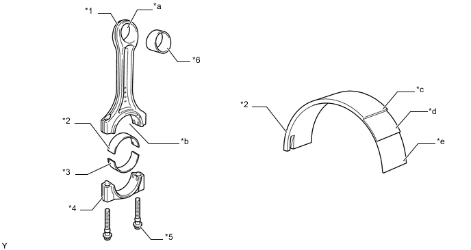
*1 Connecting Rod Sub-assembly *2 Connecting Rod Bearing (Sputter Bearing) *3 Connecting Rod Bearing *4 Connecting Rod Bearing Cap *5 Plastic Region Tightening Bolt *6 Plain Bearing *a Connecting Rod Small End Bore *b Connecting Rod Big End Bore *c Steel Backing *d Leaded Bronze or High-strength Aluminum Alloy *e Sputtered Running Layer - - -
-
-