ТОПЛИВНАЯ СИСТЕМА
-
CONSTRUCTION
-
The supply pump consists of an eccentric camshaft, a ring cam, 2 plungers, 4 check valves, a Suction Control Valve (SCV), a fuel temperature sensor, and a feed pump.
-
The 2 plungers are placed opposite each other outside of the ring cam.
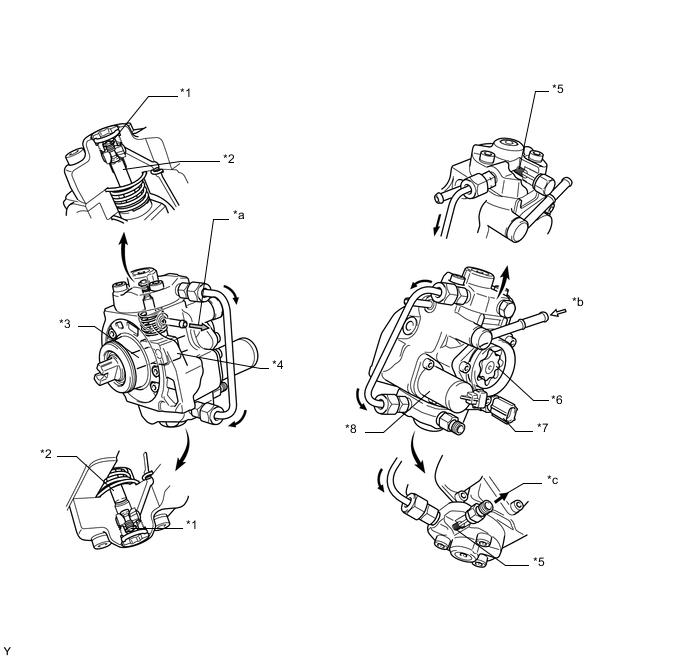
*1 Check Valve (for Suction) *2 Plunger *3 Inner Cam (Eccentric Camshaft) *4 Ring Cam *5 Check Valve (for Discharge) *6 Feed Pump *7 Fuel Temperature Sensor *8 SCV *a To Fuel Tank (for Return) *b From Fuel Tank (for Suction) *c To Common-rail Assembly - - 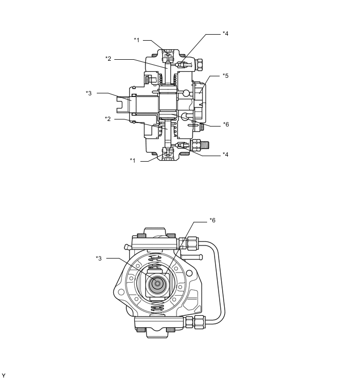
*1 Check Valve (for Suction) *2 Plunger *3 Inner Cam (Eccentric Camshaft) *4 Check Valve (for Discharge) *5 Feed Pump *6 Ring Cam -
A fuel outlet for the exhaust fuel addition injector has been added.
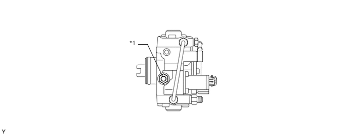
*1 Fuel Hole - -
-
-
OPERATION
-
Due to the rotation of the inner cam (eccentric camshaft), the outer cam pushes plunger "A" upward as illustrated below. The force of the spring pulls plunger "B". As a result, plunger "B" draws fuel in, and plunger "A" pumps fuel at the same time.
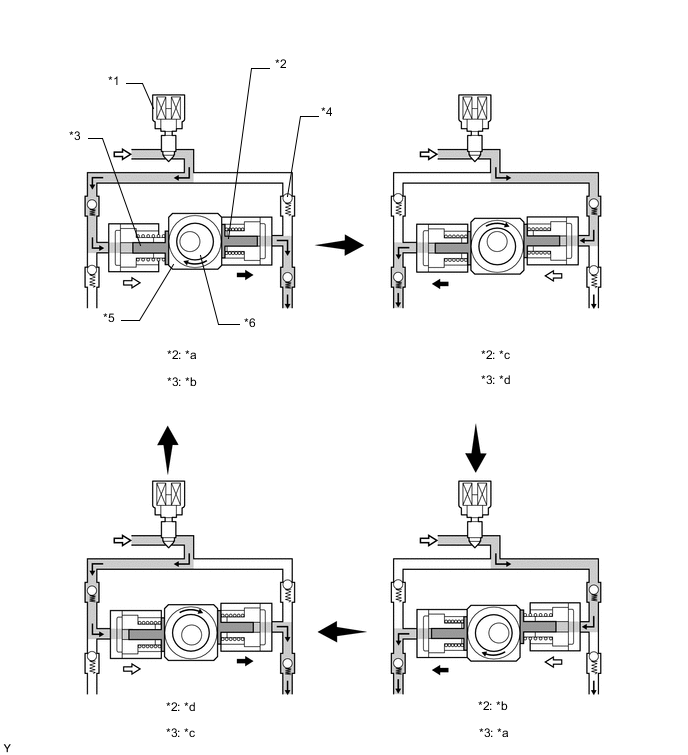
*1 SCV *2 Plunger A *3 Plunger B *4 Check Valve *5 Ring Cam *6 Inner Cam (Eccentric Camshaft) *a Pumping end *b Suction end *c Suction start *d Pumping start
-