AIR CONDITIONING SYSTEM
-
FUNCTION OF MAIN COMPONENTS
Component Function Air Conditioning Heater Single Dual Air Conditioning Control Assembly Allows operation and adjustment of the air conditioning system via switches. ○ ○ ○ Air Conditioning Amplifier Assembly Transmits and receives data between the switches and sensors. ○ ○ ○ Compressor with Pulley Assembly A continuously variable capacity type cooler compressor is used to steplessly control the refrigerant discharge capacity, thus improving comfort and achieving energy savings. ○ ○ - Blower Motor with Fan Sub-assembly High magnetic force magnets and ball bearings are used to achieve a compact and lightweight assembly. ○ ○ ○ Cooler Condenser (Condenser with Receiver Assembly) A condenser is used to improve heat exchange efficiency. ○ ○ - Heater Radiator Unit Sub-assembly A Straight Flow Aluminum (SFA)-II heater radiator is used for compactness and high performance. ○ ○ ○ No. 1 Cooler Evaporator Sub-assembly A Revolutionary super-Slim structure (RS) evaporator is used for compactness. ○ ○ ○ No.1 Cooler Thermistor Detects the temperature of the cool air past the No. 1 cooler evaporator sub-assembly and transmits the data to the air conditioning amplifier assembly. ○ ○ - Thermistor Assembly Detects ambient temperature and outputs it to the combination meter assembly. ○ ○ ○ Cooler (Room Temperature Sensor) Thermistor Detects room temperature and outputs it to the air conditioning amplifier assembly. ○ ○ - Cooler (Solar Sensor) Thermistor Detects the changes in the amount of solar energy and outputs them to the air conditioning amplifier assembly. ○ ○ - PTC Heater Assembly (Quick Heater Assembly)*1 Consists of Positive Temperature Coefficient (PTC) elements, aluminum fins, and brass plates. ○ ○ ○ Air Mix Damper Servo Sub-assembly Receives temperature setting signals via the air conditioning amplifier assembly, operates the motor, and opens and closes the air mix damper. ○ ○ ○ No. 2 Air Mix Damper Servo Sub-assembly - ○ - Recirculation Damper Servo Sub-assembly Receives fresh-air/recirculation selector operation signals via the air conditioning amplifier assembly, operates the motor, and opens and closes the fresh-air/recirculation damper. ○ ○ ○ Mode Damper Servo Sub-assembly Receives mode selector operation signals via the air conditioning amplifier assembly, operates the motor, and opens and closes the mode damper. ○ ○ ○ Clean Air Filter (Air Refiner Element) Removes pollen and other particles to provide a comfortable interior space. ○ ○ ○ Air Conditioner Pressure Sensor Detects the refrigerant pressure and sends data to the air conditioning amplifier assembly. ○ ○ - ECM Receives the signals from the E.F.I. engine coolant temperature sensor and transmits them to the air conditioning amplifier assembly. ○ ○ ○ Engine Stop and Start ECU*2 Receives engine on request signal and blower signal from the air conditioning amplifier assembly. ○ ○ ○ Radio and Display Receiver Assembly*3 Temporarily displays current information of the air conditioning system or heater system when the air conditioning control panel is operated. ○ ○ ○ Tech Tips
○: Equipped
-: Not equipped
*1: Models with PTC heater
*2: Models with stop and start system
*3: Models with touch screen system or display audio system
-
SYSTEM CONTROL
-
Control List
Control Outline Air Conditioning Heater Single Dual Neural Network Control This control is capable of effecting complex control by artificially simulating the information processing method of the nervous system of living organisms in order to establish a complex input/output relationship that is similar to a human brain. ○ ○ - Outlet Air Temperature Control In compliance with the temperature set at the temperature control switch, the neural network control calculates the outlet temperature based on the input signals from various sensors. In addition, corrections in accordance with the signals from the No. 1 cooler thermistor and the E.F.I. engine coolant temperature sensor are added to control the outlet air temperature. ○ ○ - Left and Right Independent Control The temperature setting for the driver and front passenger is controlled independently in order to provide a separate vehicle interior temperature for the right and left sides of the vehicle. Thus, air conditioning control that accommodates occupant preferences has been realized. - ○ - Blower Control Controls the blower motor with fan sub-assembly in accordance with the airflow volume that has been calculated by the neural network control based on the input signals from various sensors. ○ ○ - Air Outlet Control Automatically switches the outlets in accordance with the outlet mode ratio that has been calculated by the neural network control based on the input signals from various sensors. ○ ○ - Air Inlet Control Automatically controls the air inlet control damper in accordance with the airflow volume that has been calculated by the neural network control. ○ ○ - Refrigerant Volume Detection Control Judges a shortage of refrigerant volume based on signals from each sensor and informs the user by turning off the indicator light of the A/C switch. ○ ○ - Variable Capacity Compressor Control Controls the compressor with pulley assembly to turn it on or off and adjust the discharge capacity based on the signals from various sensors. ○ ○ - PTC Heater Control*1 When the ignition switch is turned to ON, and the blower motor is turned on, the air conditioning amplifier assembly turns on the PTC heater (quick heater assembly) if the following conditions are met.
-
E.F.I. engine coolant temperature is below specified temperature.
-
Ambient temperature is below specified temperature.
-
Tentative air mix damper opening angle is above the specified value (MAX HOT).
○ ○ ○ Engine Start Request Control*2 In order to prevent deterioration of the air conditioning performance while the engine is stopped, if all of the conditions are met while the air conditioning is operating, the air conditioning amplifier assembly sends an engine start request signal to the engine stop and start ECU, starting the engine. ○ ○ ○ Blower Customization Control During automatic air conditioning operation, the air volume can be adjusted in 3 levels using the FAST SOFT switch: MEDIUM → SOFT (small air volume) → FAST (large air volume). ○ ○ - Fresh Air Introduction While Parking System While parking, fresh air introduction mode is automatically selected. Self-diagnosis The air conditioning amplifier assembly has a self-diagnosis function. It stores any operation malfunctions in memory in the form of Diagnostic Trouble Codes (DTCs). ○ ○ - Tech Tips
○: Equipped
-: Not equipped
*1: Models with PTC heater
*2: Models with stop and start system
-
-
Neural Network Control
-
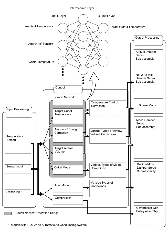
Previously, in automatic air conditioning systems without neural network control, the air conditioning amplifier assembly determined the required outlet air temperature and blower air volume in accordance with the calculation formula that has been obtained based on information received from the sensors. However, because the senses of a person are rather complex, a given temperature is sensed differently, depending on the environment in which the person is situated. For example, a given amount of solar radiation can feel comfortably warm in a cold climate, or extremely uncomfortable in a hot climate. Therefore, as a technique for effecting a higher level of control, a neural network has been adopted in the automatic air conditioning system. With this technique, the data that has been collected under varying environmental conditions is stored in the air conditioning amplifier assembly. The air conditioning amplifier assembly can then effect control to provide enhanced air conditioning comfort.
-
The neural network control consists of neurons in the input layer, intermediate layer and output layer. The input layer neurons process the input data of the ambient temperature, the amount of sunlight, and the room temperature based on the outputs of the switches and sensors, and output them to the intermediate layer neurons. Based on this data, the intermediate layer neurons adjust the strength of the links among the neurons. The sum of these is then calculated by the output layer neurons in the form of the required outlet temperature, solar correction, target airflow volume, and outlet mode control volume. Accordingly, the air conditioning amplifier assembly controls the servo motors and blower motor in accordance with the control volumes that have been calculated by the neural network control.
-
-
Refrigerant Volume Detection Control
-
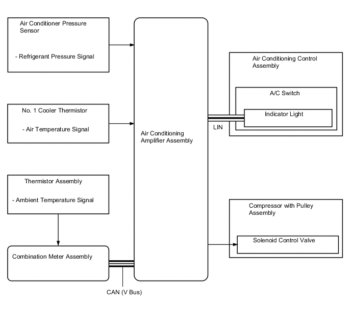
The air conditioning amplifier assembly judges the volume of refrigerant from the ambient temperature, refrigerant pressure and the temperature of the cool air just past the No. 1 cooler evaporator sub-assembly. When the air conditioning amplifier assembly judges that there is a refrigerant shortage, it turns off the indicator light of the A/C switch. At that time, the compressor with pulley assembly stops operating.
-
-
PTC Heater Control
-
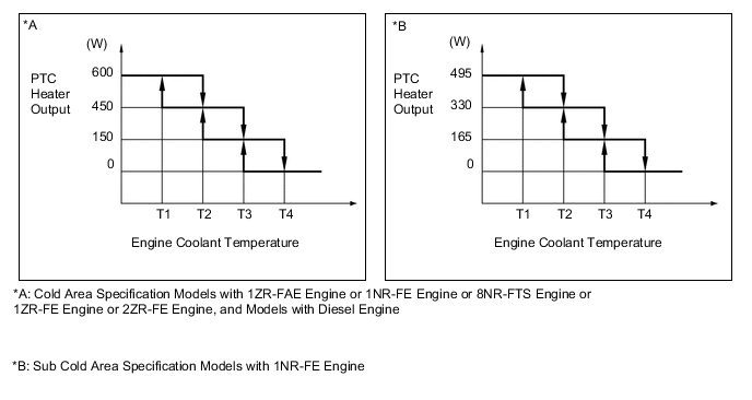
The output of the PTC heater (quick heater assembly) is controlled by the air conditioning amplifier assembly in accordance with the engine coolant temperature, engine speed, air mix setting, and electrical load (generator assembly power ratio).
-
-
Fresh Air Introduction While Parking System
-
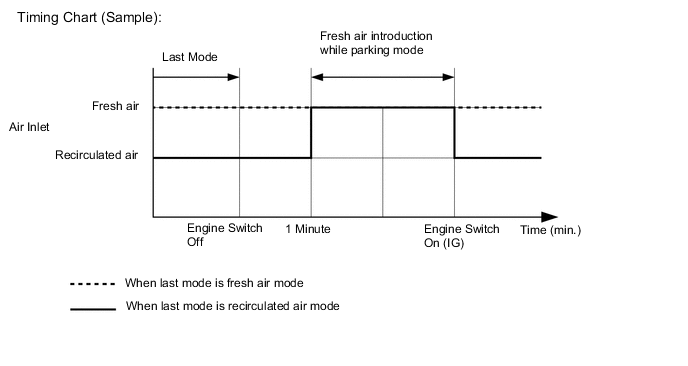
While parking, fresh air introduction mode is automatically selected to enhance ventilation and reduce any odor remaining in the air conditioning unit, thus odor during engine start-up is minimized.
-
-
-
DIAGNOSIS
-
The air conditioning amplifier assembly has a self-diagnosis function. It stores any operation malfunctions in the air conditioning system or heater system in memory in the form of Diagnostic Touble Codes (DTCs). For details, refer to the Repair Manual.
-