AIR CONDITIONING SYSTEM
-
CONSTRUCTION
-
The compressor with pulley assembly is a continuously variable capacity type with a capacity that varies in accordance with the cooling load of the air conditioning.
-
The compressor with pulley assembly consists of the shaft, lug plate, piston, shoe, crank chamber, cylinder and solenoid control valve.
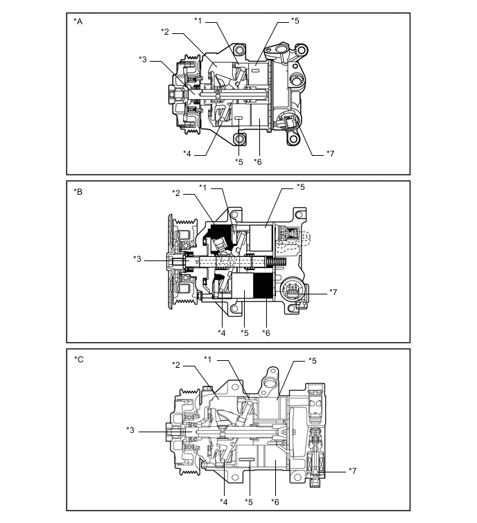
*A Models with 5TSE10C Compressor with Pulley Assembly *B Models with 5SE12C Compressor with Pulley Assembly *C Models with 6SES14C or 6SES12C Compressor with Pulley Assembly - - *1 Shoe *2 Crank Chamber *3 Shaft *4 Lug Plate *5 Piston *6 Cylinder *7 Solenoid Control Valve - - -
A cylinder-type damper is used for 5TSE10C or 6SES14C or 6SES12C compressor with pulley assembly and the torque fluctuations have been suppressed, thus making the inertia weight unnecessary. As a result, the weight of the compressor with pulley assembly has been reduced.
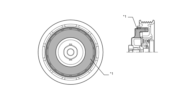
*1 Damper - - -
6 dampers are used on air conditioning systems with the 5SE12C compressor with pulley assembly. A plastic DL type air conditioning pulley contains 6 dampers to absorb the torque fluctuations of the engine and a limiter mechanism to protect the drive belt in case the compressor locks. In the event that the compressor locks, the limiter mechanism causes the spoke portion of the pulley to break, thus disconnecting the pulley from the compressor. To reduce weight, the pulley portion is made of plastic.
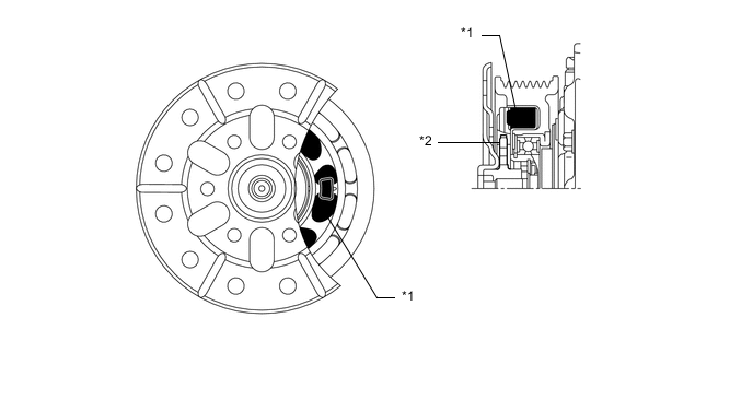
*1 Damper *2 Spoke Portion
-
-
OPERATION
-
The crank chamber is connected to the suction passage. A solenoid control valve is provided between the suction passage (low pressure) and the discharge passage (high pressure).
-
The solenoid control valve operates under duty cycle control in accordance with the signals from the air conditioning amplifier assembly.
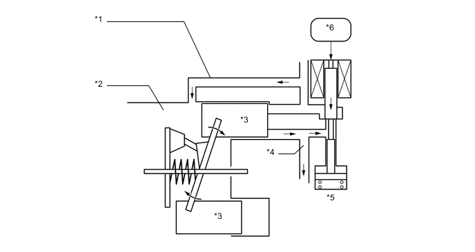
*1 Suction Passage *2 Crank Chamber *3 Piston *4 Discharge Passage *5 Solenoid Control Valve *6 Air Conditioning Amplifier Assembly -
When the solenoid control valve closes (the solenoid coil is energized), a difference in pressure is created and the pressure in the crank chamber decreases. Then, the pressure applied to the right side of the piston becomes greater than the pressure applied to the left side of the piston. This compresses the spring and tilts the lug plate. As a result, the piston stroke increases and the discharge capacity increases.
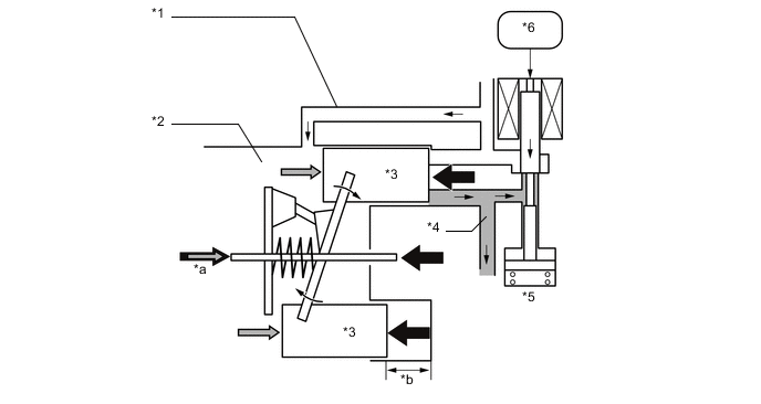
*1 Suction Passage *2 Crank Chamber *3 Piston *4 Discharge Passage *5 Solenoid Control Valve *6 Air Conditioning Amplifier Assembly *a Crank Chamber Pressure + Spring Force *b Piston Stroke: Large -
When the solenoid control valve opens (the solenoid coil is not energized), the difference in pressure disappears. Then, the pressure applied to the left side of the piston becomes the same as the pressure applied to the right side of the piston. Thus, the spring elongates and eliminates the tilt of the lag plate. As a result, there is a small piston stroke and the discharge capacity decreases.
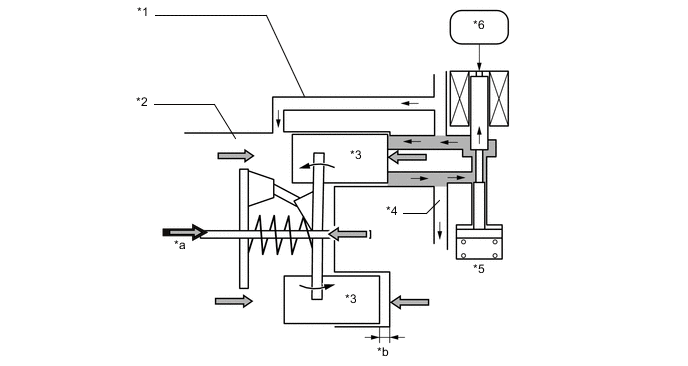
*1 Suction Passage *2 Crank Chamber *3 Piston *4 Discharge Passage *5 Solenoid Control Valve *6 Air Conditioning Amplifier Assembly *a Crank Chamber Pressure + Spring Force *b Piston Stroke: Small
-