METER / GAUGE SYSTEM
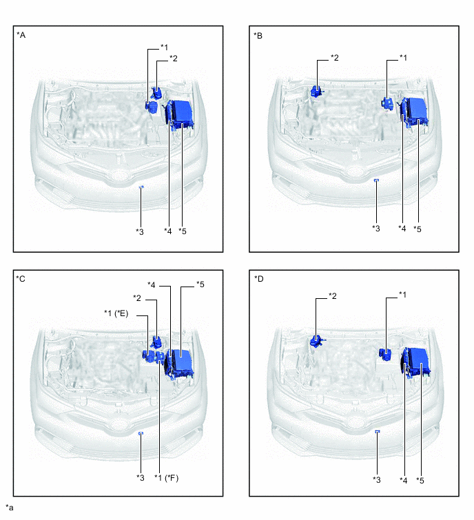
| *A | LHD Models with Gasoline Engine | *B | RHD Models with Gasoline Engine |
| *C | LHD Models with Diesel Engine | *D | RHD Models with Diesel Engine |
| *E | Except Models with Multi-mode Manual Transaxle | *F | Models with Multi-mode Manual Transaxle |
| *1 | Brake Actuator Assembly
|
*2 | Brake Master Cylinder Sub-assembly
|
| *3 | Thermistor Assembly | *4 | ECM |
| *5 | Engine Room Relay Block
|
- | - |
| *a | The illustrations shown are examples only. | - | - |
Figure 1. Hatchback and Wagon Models
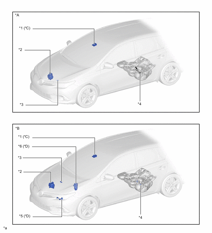
| *A | Models with Gasoline Engine | *B | Models with Diesel Engine |
| *C | Models with Pre-crash Safety System | *D | Models with 1ND-TV Engine |
| *1 | Pre-collision City Sensor | *2 | Generator Assembly |
| *3 | Oil Pressure Switch Assembly | *4 | Fuel Sender Gauge Assembly |
| *5 | Engine Oil Level Sensor | *6 | Level Warning Switch |
| *a | The illustrations shown are examples only. | - | - |
Figure 2. Sedan Models
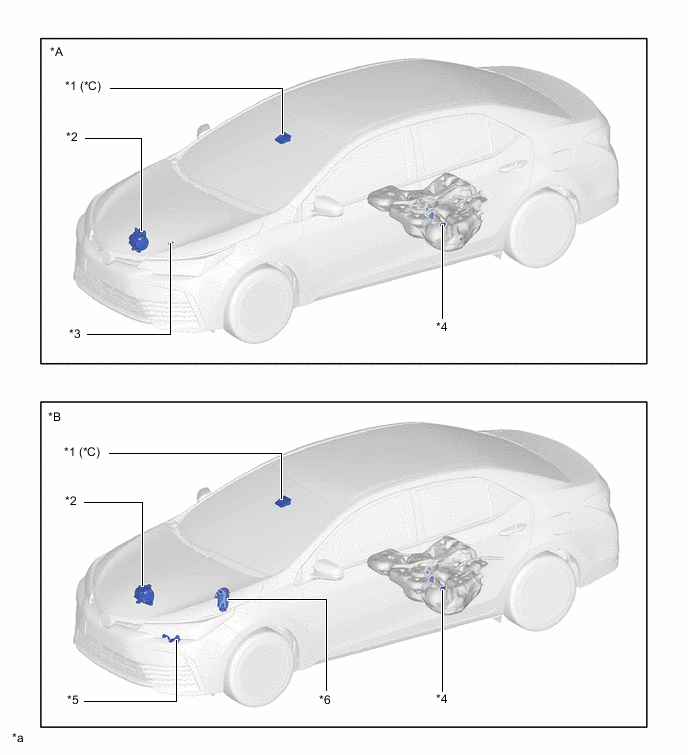
| *A | Models with Gasoline Engine | *B | Models with Diesel Engine |
| *C | Models with Pre-crash Safety System | - | - |
| *1 | Pre-collision City Sensor | *2 | Generator Assembly |
| *3 | Engine Oil Pressure Switch Assembly | *4 | Fuel Sender Gauge Assembly |
| *5 | Engine Oil Level Sensor | *6 | Level Warning Switch |
| *a | The illustrations shown are examples only. | - | - |
Figure 3. LHD Models
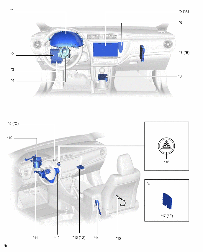
| *A | Models with Multimedia System | *B | Models with Stop and Start System |
| *C | Models with Front Fog Lights | *D | Models with Simple Intelligent Parking Assist System |
| *E | Models with Entry and Start System | - | - |
| *1 | Combination Meter Assembly | *2 | Main Body ECU (Multiplex Network Body ECU) |
| *3 | Instrument Panel Junction Block Assembly
|
*4 | Spiral Cable Sub-assembly |
| *5 | Radio and Display Receiver Assembly | *6 | Clock Assembly
|
| *7 | Engine Stop and Start ECU | *8 | Airbag Sensor Assembly |
| *9 | FR FOG Relay | *10 | Power Steering ECU Assembly |
| *11 | Headlight Dimmer Switch Assembly | *12 | Steering Pad Switch Assembly |
| *13 | Clearance Warning ECU Assembly | *14 | Front Inner Seat Belt Assembly (RH) |
| *15 | Belt Warning Occupant Detection Sensor (RH) | *16 | Hazard Warning Signal Switch Assembly |
| *17 | Certification ECU (Smart Key ECU Assembly) | - | - |
| *a | Refer to Service Bulletin for the installation position of the part. | *b | The illustrations shown are examples only. |
Figure 4. RHD Models
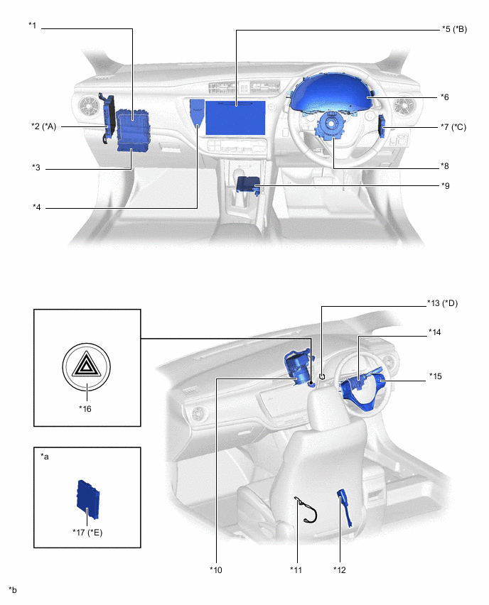
| *A | Models with Stop and Start System | *B | Models with Multimedia System |
| *C | Models with Simple Intelligent Parking Assist System | *D | Models with Front Fog Lights |
| *E | Models with Entry and Start System | - | - |
| *1 | Main Body ECU (Multiplex Network Body ECU) | *2 | Engine Stop and Start ECU |
| *3 | Instrument Panel Junction Block Assembly
|
*4 | Clock Assembly
|
| *5 | Radio and Display Receiver Assembly | *6 | Combination Meter Assembly |
| *7 | Clearance Warning ECU Assembly | *8 | Spiral Cable Sub-assembly |
| *9 | Airbag Sensor Assembly | *10 | Power Steering ECU Assembly |
| *11 | Belt Warning Occupant Detection Sensor (LH) | *12 | Front Seat Inner Belt Assembly (LH) |
| *13 | FR FOG Relay | *14 | Headlight Dimmer Switch Assembly |
| *15 | Steering Pad Switch Assembly | *16 | Hazard Warning Signal Switch Assembly |
| *17 | Certification ECU (Smart Key ECU Assembly) | - | - |
| *a | Refer to Service Bulletin for the installation position of the part. | *b | The illustrations shown are examples only. |
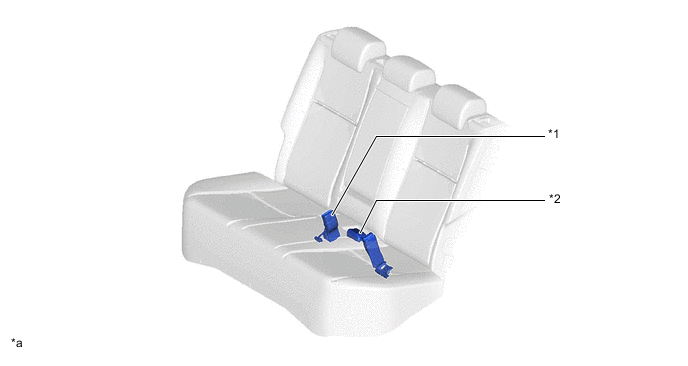
| *1 | Rear Inner Center Seat with Belt Assembly (RH) | *2 | Rear Inner Center Seat with Belt Assembly (LH) |
| *a | This illustration is an example only. | - | - |