SIMPLE INTELLIGENT PARKING ASSIST SYSTEM(for Sedan)
-
FUNCTION OF MAIN COMPONENTS
-
The main components of the simple intelligent parking assist system have the following functions:
Component Function No. 2 Ultrasonic Sensor (2) Detect parked vehicles, curbs, walls and send information to the clearance warning ECU assembly. IPA Main Switch Assembly Operating this switch allows the operation of the simple intelligent parking assist system to be enabled or disabled. Clearance Warning ECU Assembly
-
Controls the functions of the simple intelligent parking assist system based on signals from the ultrasonic sensors, switches and ECUs.
-
Determines if enough parking space is available based on signals from the ultrasonic sensors (front side LH/RH).
-
Determines the parking direction based on steering wheel position information and the turn signal switch operation state.
-
Sends a message display request signal or buzzer sound signal to the combination meter assembly in accordance with the operation condition and state of the simple intelligent parking assist system.
-
Controls the TOYOTA parking assist-sensor system during automatic steering mode, and sends a display request signal to the combination meter assembly or a buzzer sound signal to each clearance warning buzzer, in accordance with the position of an obstruction or the distance from the vehicle to the obstruction.
Combination Meter Assembly Multi-information Display
-
Displays information in accordance with the operation condition and state of the simple intelligent parking assist system, based on the received display request signal.
-
Displays the position of an obstruction and the distance between the vehicle and the obstruction.
-
Displays information such as a malfunction to inform the driver.
-
Sends turn signal information to the clearance warning ECU assembly.
-
The automatic steering mode indicator illuminates when automatic steering is started while the simple intelligent parking assist system is operating.
Buzzer Sounds in accordance with the operation condition and state of the simple intelligent parking assist system, based on the received buzzer sound signal. Headlight Dimmer Switch Assembly Sends a turn signal to the combination meter assembly. Spiral Cable with Sensor Sub-assembly
-
Steering Sensor
Detects the angle of the steering wheel, and sends a signal to the clearance warning ECU assembly. Power Steering ECU Assembly
-
Performs steering control upon receiving signals such as the steering control signal from the clearance warning ECU assembly.
-
Sends vehicle condition signals such as the EPS fail-safe signal and steering control status signal to the clearance warning ECU assembly.
No. 1/No. 3 Ultrasonic Sensor (8) Detect the distance between the vehicle and an obstruction and send information to the clearance warning ECU assembly. (Automatic Steering Mode) No. 1 Clearance Warning Buzzer Sounds a buzzer in accordance with the distance to the obstruction in front of the vehicle to inform the driver. No. 2 Clearance Warning Buzzer Sounds a buzzer in accordance with the distance to the obstruction behind the vehicle to inform the driver. Back-up Light Switch Assembly*1 Sends an R shift position signal to the clearance warning ECU assembly. Park/Neutral Position Switch Assembly*2 Transmits the shift position signal to the ECM. ECM Sends vehicle condition signals such as the engine speed signal and shift position signal*4 to the clearance warning ECU assembly. Main Body ECU (Multiplex Network Body ECU) Transmits steering wheel position information (right or left) to the clearance warning ECU assembly. Air Conditioning Amplifier Assembly Sends outside temperature information to the clearance warning ECU assembly to adjust the distance rate from the ultrasonic sensors. Brake Actuator Assembly
-
Skid Control ECU
-
Sends signals such as a wheel speed signal and brake system condition signal to the clearance warning ECU assembly.
-
Transmits the VSC OFF switch signal to the clearance warning ECU assembly.
-
Transmits the operation state signal of the brake control system (VSC, TRC or ABS) to the clearance warning ECU assembly.
Engine Stop and Start ECU*3
-
Sends the stop and start system operation condition signal to the clearance warning ECU assembly.
-
Receives a simple intelligent parking assist system operation signal from the clearance warning ECU assembly and starts the engine If the engine is being stopped due to stop and start system operation, canceling stop and start system operation during simple intelligent parking assist system operation.
*1: Models with manual transaxle or multi-mode manual transaxle
*2: Models with multidrive/continuously variable transaxle
*3: Models with stop and start system
-
-
-
SYSTEM CONTROL
-
Parking Space Detection Mode
Tech Tips
-
The simple intelligent parking assist system detects parking spaces on the front passenger's side of the vehicle and assists with parking in a detected space.
-
When parking in a space on the driver's side of the vehicle, move the turn signal switch to indicate turning on the driver's side. Leave the turn signal switch in that position until automatic steering begins.
-
The operation condition of starting parking space detection mode is as follows:
-
Engine has started.
-
IPA main switch assembly is on.
-
Shift lever is in a position other than R.
-
Vehicle speed is approximately 30 km/h (18 mph) or less.
-
Brake control system (VSC or TRC, ABS) is operational (VSC OFF switch is ON).
-
-
Turn the IPA main switch assembly on with the vehicle driving at 30 km/h (18 mph) or less.
-
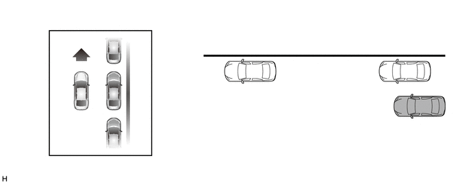
The multi-information display changes to the parking space detection screen when the simple intelligent parking assist system is operating.
-
Drive the vehicle while maintaining a distance of approximately 1 m (3 ft.) from the parked vehicles.
Tech Tips
Drive the vehicle as parallel to the parked vehicles and curb as possible.
-
Lower vehicle speeds allow the system to assist in parking the vehicle more parallel to the parked vehicles and curb, and in a more proper position between vehicles at the front and rear of a parking space.
Tech Tips
-
The required length for a parking space to be detected is the total vehicle length plus approximately 1 m (3 ft.).
-
Maintain a vehicle speed of 30 km/h (18 mph) or less.
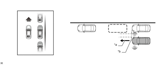
*a Vehicle speed of 30 km/h (18 mph) or less *b Approximately 1 m (3 ft.) -
-
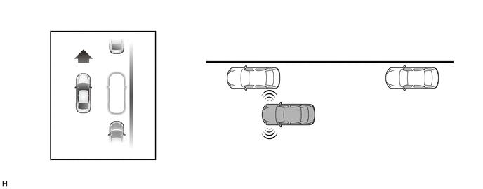
When the multi-information display changes, reduce the vehicle speed. Move the vehicle forward slowly until the buzzer sounds.
-
Stop the vehicle when the buzzer sounds. The multi-information display will change.
Note
Visually check that the detected space is safe for parking.
Tech Tips
If the vehicle moves 10 m (32 ft.) or more after the buzzer sounds, detection of a new parking space will begin.
-
-
Automatic Steering Mode
-
The operation condition of starting automatic steering mode is as follows:
-
Engine has started.
-
IPA main switch assembly is on.
-
Allowable parking space area has been detected.
-
Shift lever is in R.
-
Vehicle speed is approximately 6 km/h (3 mph) or less.
-
Brake control system (VSC or TRC, ABS) is operational (VSC OFF switch is ON).
-
-
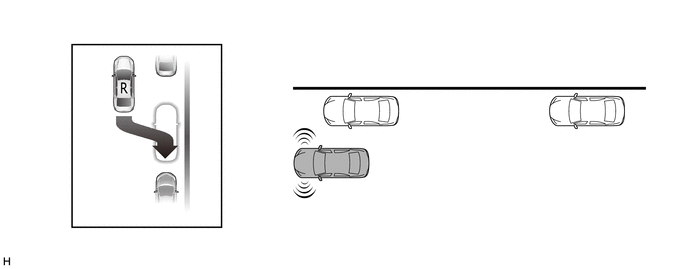
Move the shift lever to R.
-
The multi-information display will change and automatic steering will begin. While taking care not to catch your hands on the steering wheel and checking the safety of the surrounding area, reverse the vehicle slowly by operating the accelerator and brake pedals.
Tech Tips
-
When automatic steering is started, the automatic steering mode indicator is displayed on the multi-information display.
-
During automatic steering, maintain a vehicle speed of 6 km/h (3 mph) or less.
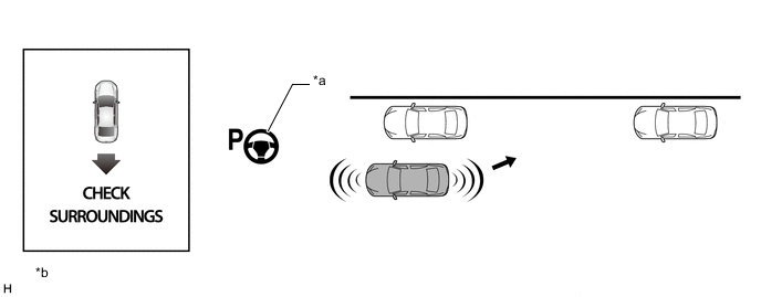
*a Automatic Steering Mode Indicator *b The illustrations shown are examples only. The illustrations may differ from the actual vehicle screens. -
-
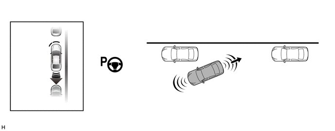
When the multi-information display changes, reduce the vehicle speed. While checking the safety of the area behind the vehicle, reverse the vehicle slowly. (*A)
-
When the No. 2 clearance warning buzzer sounds continuously, completely stop the vehicle immediately. The multi-information display will change when the warning buzzer starts sounding continuously. (*B)
-
When the shift lever is moved to D*1, E, M*2 or 1*3, automatic steering starts. (*C)
-
*1: Models with multidrive/continuously variable transaxle
-
*2: Models with multi-mode manual transaxle
-
*3: Models with manual transaxle
Tech Tips
While the steering wheel is turning, keep the vehicle at a complete stop.
-
-
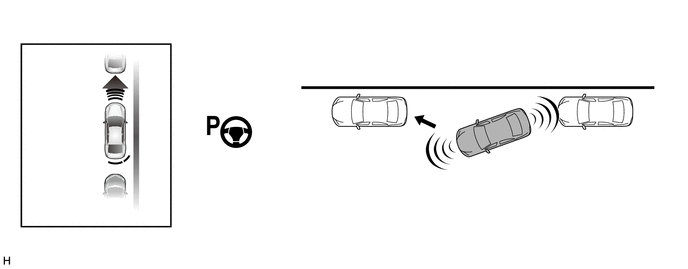
When the steering wheel stops turning, move the vehicle forward slowly while checking the safety of the area in front of the vehicle. (*D)
-
When the No. 1 clearance warning buzzer sounds continuously, completely stop the vehicle immediately. The multi-information display will change when the warning buzzer starts sounding continuously. (*E)
-
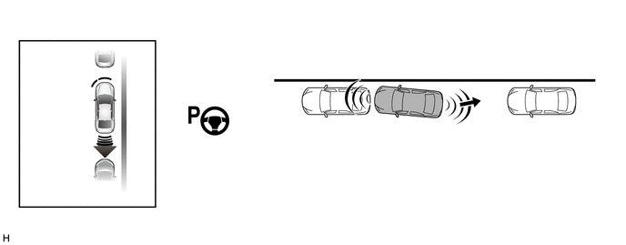
When the shift lever is moved to R, automatic steering starts. (*F)
Tech Tips
While the steering wheel is turning, keep the vehicle at a complete stop.
-
When the steering wheel stops turning, reverse the vehicle slowly while checking the safety of the area behind the vehicle.
-
Repeat steps (*A) through (*F) until the parking assist operation has completed. When the parking assist operation has completed, the buzzer sounds and the multi-information display changes.
Tech Tips
Adjust the vehicle position and/or angle as necessary to complete parking the vehicle.
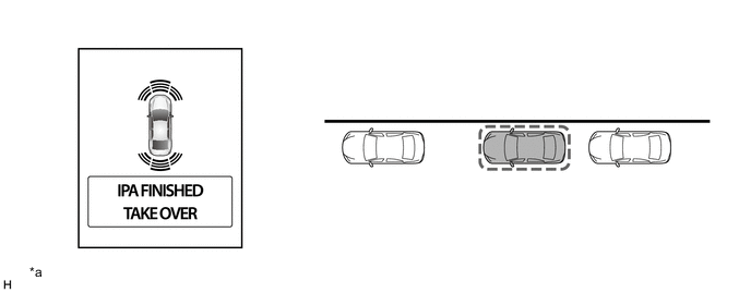
*a The illustrations shown are examples only. The illustrations may differ from the actual vehicle screens. - -
-
-
-
FUNCTION
-
Warning Message Function
-
A warning message appears on the multi-information display under the following conditions. Warning messages appear in the same language that has been selected for the multi-information display.
Messages Appearing at Multi-information Display Warning Message Outline CHECK SURROUNDINGS This message appears when automatic steering mode is started. IPA FINISHED, TAKE OVER This message appears when the parking assist is finished (parking is complete). IPA CANCELED, TAKE OVER, CHECK IPA This message appears when the operation of the simple intelligent parking assist system has been canceled because a malfunction is detected in the system components. CHECK IPA This message appears for 4 seconds if the IPA main switch assembly is turned on when a malfunction is detected in the system components. IPA SLOT NOT DETECTED, SPEED TOO HIGH This message appears when the parking space cannot be detected because vehicle speed exceeded 30 km/h (18 mph) in parking space detection mode. IPA CANCELED, TAKE OVER, SPEED TOO HIGH This message appears in the following situations:
-
During parking space detection, detection is canceled because vehicle speed exceeded 50 km/h (31 mph).
-
During automatic steering, operation is canceled because vehicle speed exceeded 6 km/h (3 mph).
IPA CANCELED, TAKE OVER, DRIVER INTERVENED This message appears when automatic steering operation is canceled because the user operated the steering wheel during automatic steering. IPA CANCELED TAKE OVER, TRC/VSC IS OFF This message appears when the operation of the simple intelligent parking assist system is canceled because the VSC OFF switch was pressed to disable the VSC while the simple intelligent parking assist system was operating. IPA CANCELED TAKE OVER, TRC/VSC/ABS ACTIVATED This message appears when the operation of the simple intelligent parking assist system is canceled because the brake control system (VSC, TRC or ABS) was activated while the simple intelligent parking assist system was operating. IPA CANCELED TAKE OVER, TIMEOUT This message appears in the following situations:
-
The operation of the simple intelligent parking assist system is canceled because 6 minutes have elapsed since the IPA main switch assembly was turned on and automatic steering mode has not been started.
-
Automatic steering is canceled because 6 minutes have elapsed since automatic steering mode was started and the parking assist operation has not been finished (parking is not complete).
-
Automatic steering is canceled because the total of vehicle stop time during automatic steering exceeded 2 minutes.
IPA NOT AVAILABLE, SPEED TOO HIGH This message appears when the IPA main switch assembly is turned on at a vehicle speed of 50 km/h (31 mph) or more. IPA NOT AVAILABLE, TRC/VSC IS OFF This message appears when the IPA main switch assembly is turned on with the brake control system (VSC, TRC or ABS) disabled (VSC OFF switch OFF). IPA NOT AVAILABLE This message appears in the following situations:
-
The simple intelligent parking assist system is not available due to temporary overheating of the power steering system.
-
The engine has not started.
-
Battery voltage is low.
-
A malfunction is detected in the system components.
IPA CANCELED, TAKE OVER
-
This message appears when the operation of the simple intelligent parking assist system is canceled due to the following:
-
The IPA main switch assembly was turned off.
-
The power steering system temporarily overheated.
-
The engine stopped.
-
Operating the steering wheel became difficult due to reduced tire inflation pressure, tire abrasion, road surface condition or steep downhill, disabling parking operation to the target parking space any further.
-
During automatic steering, the shift lever was moved to a position other than R before the vehicle entered the target parking space.
-
The shift lever was moved to R while the target parking space was being detected (detection is not complete).
-
After the target parking space was detected, the shift lever was moved to R and the vehicle was backed up by 1 m (3.3 ft.) or more.
-
The IPA main switch was turned on with the shift lever in R.
-
A malfunction was detected in the system components.
IPA NOT AVAILABLE, STOP THE VEHICLE, TURN WHEEL FROM LEFT END TO RIGHT END Appears when the steering wheel was operated while the cable was disconnected from the negative (-) battery terminal and then reconnected. -
-
-
Calibration Following Parts Replacement
-
The items listed below must always be adjusted whenever one of the following conditions occurs. For details, refer to the Repair Manual.
Adjustment Items Condition Memorize maximum steering angle The cable was disconnected from the negative (-) battery terminal and then reconnected and, "IPA NOT AVAILABLE, STOP THE VEHICLE, TURN WHEEL FROM LEFT END TO RIGHT END" is displayed. Initialize simple intelligent parking assist system
-
The spiral cable with sensor sub-assembly was removed and installed or a spiral cable with sensor sub-assembly connector was disconnected and reconnected.
-
The spiral cable with sensor sub-assembly was replaced.
-
The clearance warning ECU assembly was replaced.
-
-
-
Initialization
-
Initialization can be performed in initialize mode of the simple intelligent parking assist system. For details on the procedure required to perform initialization, refer to the Repair Manual.
-
-
-
FAIL-SAFE
-
The table below indicates malfunction detection items for the sensors and ECUs in this system.
Malfunctioning Part Detection Item Simple Intelligent Parking Assist System Function ON
(Parking Space Detection Mode or Automatic Steering Mode)
OFF No. 2 Ultrasonic Sensor
-
Malfunction
-
Open circuit
Operation of the simple intelligent parking assist system is canceled, and the following message is displayed on the multi-information display:
-
"IPA CANCELED, TAKE OVER, CHECK IPA"
When the IPA main switch assembly is turned on, the following message is displayed for 4 seconds:
-
"CHECK IPA"
Spiral Cable with Sensor Sub-assembly
- Steering Sensor
-
Sensor malfunction is detected
-
Sensor open circuit signal is detected
-
Communication malfunction between the spiral cable with sensor sub-assembly (steering angle sensor) and clearance warning ECU assembly
Operation of the simple intelligent parking assist system is canceled, and the following message is displayed on the multi-information display:
-
"IPA CANCELED, TAKE OVER, CHECK IPA"
When the IPA main switch assembly is turned on, the following message is displayed for 4 seconds:
-
"CHECK IPA"
Clearance Warning ECU Assembly Malfunction of clearance warning ECU assembly Stops system operation Power Steering ECU Assembly Malfunction of power steering ECU assembly Operation of the simple intelligent parking assist system is canceled, and the following message is displayed on the multi-information display:
-
"IPA CANCELED, TAKE OVER, CHECK IPA"
When the IPA main switch assembly is turned on, the following message is displayed for 4 seconds:
-
"CHECK IPA"
-
-
-
DIAGNOSIS
-
If a system malfunction is detected, the clearance warning ECU assembly stores Diagnostic Trouble Codes (DTCs) in its memory. For details, refer to the Repair Manual.
-