TOYOTA PARKING ASSIST-SENSOR SYSTEM(except Hatchback)
-
FUNCTION OF MAIN COMPONENTS
Component Function No. 1/No. 2/No. 4 Ultrasonic Sensor (10)*1 Detects the distance between the vehicle and an obstacle. No. 1/No. 2/No. 3 Ultrasonic Sensor (10)*2 No. 1 Clearance Warning Buzzer (Front) Sounds to inform the driver according to the distance to the obstacle. No. 2 Clearance Warning Buzzer (Rear) Combination Meter Assembly Multi-information Display
-
Displays the location of the obstacle and the approximate distance between the vehicle and the obstacle.
-
Displays an indication of a malfunction or freezing of an ultrasonic sensor to inform the driver.
Master Warning Light Illuminates in accordance with the indication on the multi-information display. Back Sonar or Clearance Sonar Switch Assembly Operating this switch allows the operation of the TOYOTA parking assist-sensor system to be enabled or disabled. Clearance Warning ECU Assembly
-
Judges the approximate distance between the vehicle and an obstacle based on signals from the ultrasonic sensors. Output signals are sent to the multi-information display.
-
Sounds the No. 1 or No. 2 clearance warning buzzer.
Air Conditioning Amplifier Assembly Sends outside temperature information to the clearance warning ECU assembly to adjust the distance rate from the ultrasonic sensors. Main Body ECU (Multiplex Network Body ECU) Sends the parking brake signal to the clearance warning ECU assembly.*3 ECM Transmits the shift position signals to the clearance warning ECU assembly.*4 Brake Actuator Assembly
- Skid Control ECU
Sends the wheel speed signal to the clearance warning ECU assembly. Back-up Light Switch Assembly*3 Sends the shift position signals to the clearance warning ECU assembly. Park/Neutral Position Switch Assembly*4 Sends the shift position signals to the ECM. *1: Wagon Models
*2: Sedan Models
*3: Models with manual transaxle or multi-mode manual transaxle
*4: Models with multidrive/continuously variable transaxle
-
-
FUNCTION
-
The operating condition of each sensor differs according to its installed position as shown in the table below:
Installation Position Operating Condition Front Corner
-
Ignition switch is ON.
-
System is activated.*1
-
Parking brake switch assembly is off.*2
-
Shift lever is in a position other than P.*3
-
Vehicle speed is approximately 10 km/h (6 mph) or less.
Front Center Front Side Rear Corner
-
Ignition switch is ON.
-
System is activated.*1
-
Back-up light switch is on.*2
-
Shift lever is in R.*3
Rear Center *1: Even if the back sonar or clearance sonar switch assembly is off, the system is activated when the simple-intelligent parking assist system is operating.
*2: Models with manual transaxle or multi-mode manual transaxle
*3: Models with multidrive/continuously variable transaxle
-
-
No. 1/No. 2 Clearance Warning Buzzer
-
Depending on the detection distance and the detection area, the sound pattern of the No. 1 clearance warning buzzer will vary.
Detection Area Detection Distance (mm (in.)) Buzzer Sound Pattern On (msec.) Off (msec.) Front Corner Long 500 +/- 50 to 375 +/- 37.5 (19.7 +/- 2.0 to 14.8 +/- 1.5) 150 +/- 15 150 +/- 15 Middle 375 +/- 37.5 to 250 +/- 25 (14.8 +/- 1.5 to 9.8 +/- 1.0) 75 +/- 7.5 75 +/- 7.5 Short 250 +/- 25 or less (9.8 +/- 1.0 or less) Continuous Sound 0 Front Center Longest 1000 +/- 100 to 550 +/- 55 (39.4 +/- 3.9 to 21.7 +/- 2.2) 150 +/- 15 650 +/- 15 Long 550 +/- 55 to 425 +/- 42.5 (21.7 +/- 2.2 to 16.7 +/- 1.7) 150 +/- 15 150 +/- 15 Middle 425 +/- 42.5 to 300 +/- 30 (16.7 +/- 1.7 to 11.8 +/- 1.2)*1 75 +/- 7.5 75 +/- 7.5 425 +/- 42.5 to 250 +/- 25 (16.7 +/- 1.7 to 9.8 +/- 1.0)*2 Short 300 +/- 30 or less (11.8 +/- 1.2 or less)*1 Continuous Sound 0 250 +/- 25 or less (9.8 +/- 1.0 or less)*2 Front Side Short 250 +/- 25 or less (9.8 +/- 1.0 or less) Continuous Sound 0 *1: While the simple-intelligent parking assist system is not operating
*2: While the simple-intelligent parking assist system is operating
-
Depending on the detection distance and the detection area, the sound pattern of the No. 2 clearance warning buzzer will vary.
Detection Area Detection Distance (mm (in.)) Buzzer Sound Pattern On (msec.) Off (msec.) Rear Corner Long 500 +/- 50 to 375 +/- 37.5 (19.7 +/- 2.0 to 14.8 +/- 1.5) 150 +/- 15 150 +/- 15 Middle 375 +/- 37.5 to 250 +/- 25 (14.8 +/- 1.5 to 9.8 +/- 1.0) 75 +/- 7.5 75 +/- 7.5 Short 250 +/- 25 or less (9.8 +/- 1.0 or less) Continuous Sound 0 Rear Center Longest 1500 +/- 150 to 550 +/- 55 (59.1 +/- 5.9 to 21.7 +/- 2.2) 150 +/- 1.5 650 +/- 65 Long 550 +/- 55 to 425 +/- 42.5 (21.7 +/- 2.2 to 16.7 +/- 1.7) 150 +/- 1.5 150 +/- 1.5 Middle 425 +/- 42.5 to 300 +/- 30 (16.7 +/- 1.7 to 11.8 +/- 1.2)*1 75 +/- 7.5 75 +/- 7.5 425 +/- 42.5 to 250 +/- 25 (16.7 +/- 1.7 to 9.8 +/- 1.0)*2 Short 300 +/- 30 or less (11.8 +/- 1.2 or less)*1 Continuous Sound 0 250 +/- 25 or less (9.8 +/- 1.0 or less)*2 *1: While the simple-intelligent parking assist system is not operating
*2: While the simple-intelligent parking assist system is operating
-
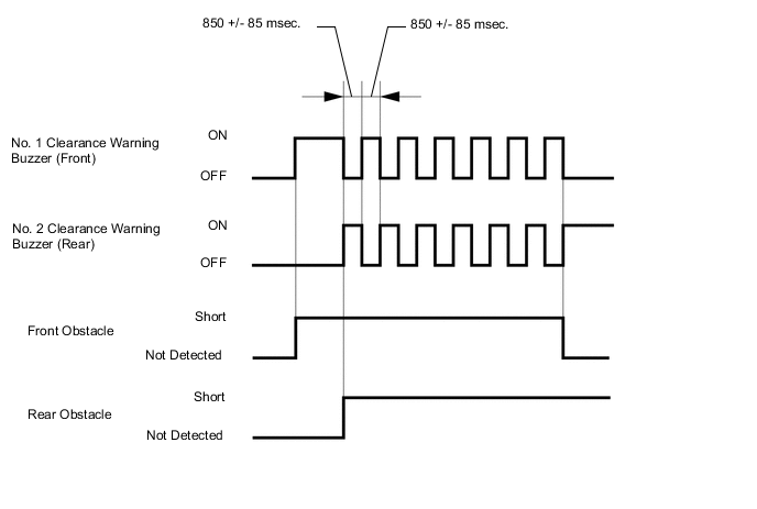
The ultrasonic sensors are divided into 2 groups: a front section group (front corners, front center and front sides) and a rear section group (rear corners and rear center). If multiple ultrasonic sensors detect obstructions at the same time, the No. 1/No. 2 clearance warning buzzer sounds as follows, in accordance with the detection distance and detection area of each group:
Buzzer Sound Pattern ON/OFF Time (msec.) Detection Distance Front Section Short Middle Long Longest Not detected Rear Section Short Timing 1 Continuous Sound (Rear) Continuous Sound (Rear) Continuous Sound (Rear) Continuous Sound (Rear) Middle Continuous Sound (Front) 75/75 (*) 75/75 (Rear) 75/75 (Rear) 75/75 (Rear) Long Continuous Sound (Front) 75/75 (Front) 150/150 (*) 150/150 (Rear) 150/150 (Rear) Longest Continuous Sound (Front) 75/75 (Front) 150/150 (Front) 150/650 (*) 150/650 (Rear) Not detected Continuous Sound (Front) 75/75 (Front) 150/150 (Front) 150/650 (Front) None *: The buzzer of the front or rear sensor, which is closest to the obstacle, sounds.
Figure 1. Timing 1
-
-
Multi-information Display
-
The location of an obstacle and the approximate distance between the vehicle and the obstacle are displayed on the multi-information display.
-
The number of lines shown on the display changes based on the actual distance and flashes when the distance is short.
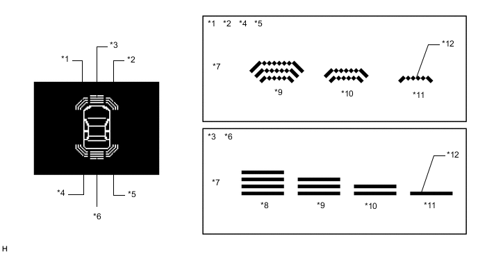
*1 Front Corner LH/Front Side LH *2 Front Corner RH/Front Side RH *3 Front Center *4 Rear Corner LH *5 Rear Corner RH *6 Rear Center *7 Distance *8 Longest *9 Long *10 Middle *11 Short *12 Flashes -
A screen displaying a warning message indicating an ultrasonic sensor malfunction, ultrasonic sensor freezing, or presence of foreign matter on the ultrasonic sensor, is displayed on the multi-information display. The warning message appears in the same language that has been selected by the language selector of the multi-information display.

-
-
Detection Area
-
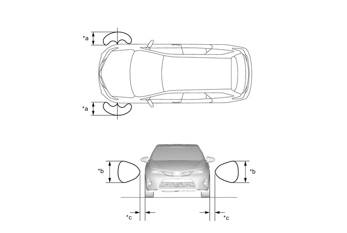
The detection areas of the ultrasonic sensor are as shown in the following illustration.
-
These detection areas are applicable when positioning a 60 mm (2.36 in.) diameter pole parallel or perpendicular to the ground. The ranges vary depending on the measuring method and type of obstacle.
Figure 2. Corners (Wagon Models)
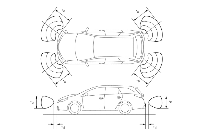
*a Approximately 500 mm (19.7 in.) *b Approximately 650 mm (25.6 in.) *c Approximately 550 mm (21.7 in.) *d Approximately 100 mm (3.9 in.) Figure 3. Center (Wagon Models)
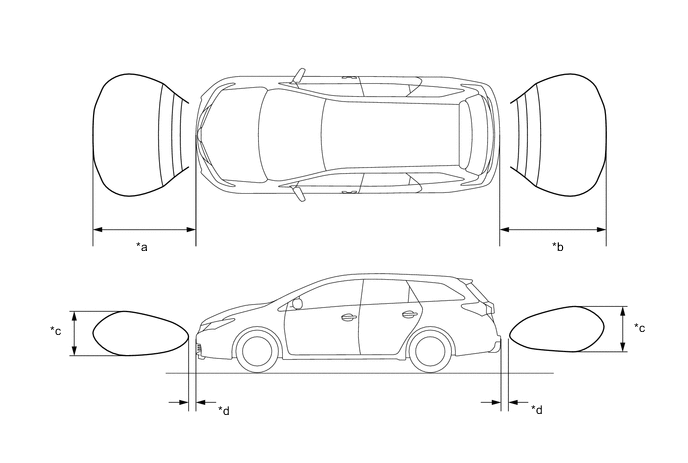
*a Approximately 1000 mm (39.4 in.) *b Approximately 1500 mm (59.1 in.) *c Approximately 650 mm (25.6 in.) *d Approximately 100 mm (3.9 in.) Figure 4. Sides (Wagon Models)
*a Approximately 250 mm (9.8 in.) *b Approximately 400 mm (15.7 in.) *c Approximately 100 mm (3.9 in.) - - Figure 5. Corners (Sedan Models)
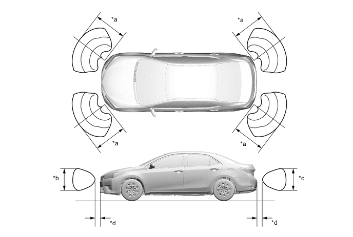
*a Approximately 500 mm (19.7 in.) *b Approximately 650 mm (25.6 in.) *c Approximately 550 mm (21.7 in.) *d Approximately 100 mm (3.9 in.) Figure 6. Center (Sedan Models)
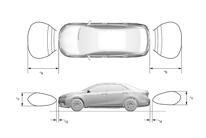
*a Approximately 1000 mm (39.4 in.) *b Approximately 1500 mm (59.1 in.) *c Approximately 650 mm (25.6 in.) *d Approximately 100 mm (3.9 in.) Figure 7. Sides (Sedan Models)

*a Approximately 250 mm (9.8 in.) *b Approximately 400 mm (15.7 in.) *c Approximately 100 mm (3.9 in.) - -
-
-
-
DIAGNOSIS
-
If a system malfunction is detected, the clearance warning ECU assembly stores Diagnostic Trouble Codes (DTCs) in its memory. For details, refer to the Repair Manual.
-