TOYOTA PARKING ASSIST-SENSOR SYSTEM(except Sedan)
-
FUNCTION OF MAIN COMPONENTS
Component Function No. 2 Ultrasonic Sensor (2) Detects the distance between the vehicle and an obstacle. No. 1 Ultrasonic Sensor (8*1/4*2) No. 3 Ultrasonic Sensor (4)*2 No. 1 Clearance Warning Buzzer (Front) Sounds to inform the driver according to the distance to the obstacle. No. 2 Clearance Warning Buzzer (Rear) Combination Meter Assembly TOYOTA Parking Assist-sensor System Indication Light Illuminates to inform the driver when the system operation conditions are met. Multi-information Display
-
Displays the location of the obstacle and the approximate distance between the vehicle and the obstacle.
-
Displays an indication of a malfunction or freezing of a No. 1/No. 2/No. 3 ultrasonic sensor to inform the driver.
Master Warning Light Illuminates in accordance with the indication on the multi-information display. Radio and Display Receiver Assembly
-
Displays the location of an obstacle and the approximate distance between the vehicle and the obstacle.
-
Displays an indication of a malfunction of a No. 1/No. 2/No. 3 ultrasonic sensor to inform the driver.
-
The sound volume can be chosen on the setup screen for the TOYOTA parking assist-sensor system.
-
Transmits the setup signal for the TOYOTA parking assist-sensor system to the clearance warning ECU assembly.
Steering Pad Switch Assembly Sends operation signals from switches such as the up switch, down switch, right switch, light switch and enter switch, to the spiral cable with sensor sub-assembly. Spiral Cable with Sensor Sub-assembly Sends operation signals from the steering pad switch assembly to the combination meter assembly. Clearance Warning ECU Assembly
-
Judges the approximate distance between the vehicle and an obstacle based on signals from the No. 1/No. 2/No. 3 ultrasonic sensors. Output signals are sent to the multi-information display.
-
Sounds the No. 1 or No. 2 clearance warning buzzer.
Air Conditioning Amplifier Assembly Sends outside temperature information to the clearance warning ECU assembly to adjust the distance rate from the No. 1/No. 2/No. 3 ultrasonic sensors. Main Body ECU (Multiplex Network Body ECU) Sends the parking brake signal to the clearance warning ECU assembly.*3 Back-up Light Switch Assembly*3 Sends the shift position signals to the clearance warning ECU assembly. Park/Neutral Position Switch Assembly*4 Sends the shift position signals to the ECM. ECM Transmits the shift position signals to the clearance warning ECU assembly.*4 Brake Actuator Assembly
-
Skid Control ECU
Sends the wheel speed signal to the clearance warning ECU assembly. *1: Hatchback Models
*2: Wagon Models
*3: Models with manual transaxle or multi-mode manual transaxle
*4: Models with multidrive/continuously variable transaxle
-
-
SYSTEM CONTROL
-
Detection Area
-
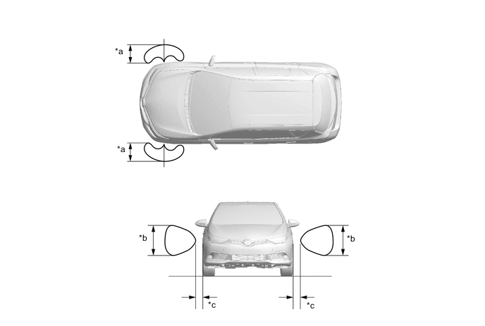
The detection areas of the No. 1/No. 2/No. 3 ultrasonic sensor are as shown in the following illustration.
-
These detection areas are applicable when positioning a 60 mm (2.36 in.) diameter pole parallel or perpendicular to the ground. The ranges vary depending on the measuring method and type of obstacle.
Figure 1. Corners (Hatchback Models)
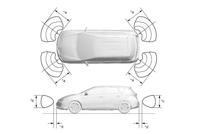
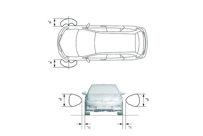
*a Approximately 500 mm (19.7 in.) *b Approximately 650 mm (25.6 in.) *c Approximately 550 mm (21.7 in.) *d Approximately 100 mm (3.9 in.) Figure 2. Corners (Wagon Models)
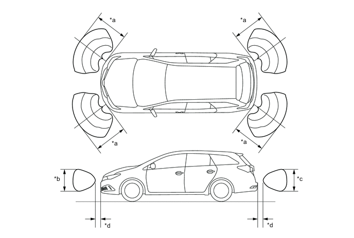
*a Approximately 500 mm (19.7 in.) *b Approximately 650 mm (25.6 in.) *c Approximately 550 mm (21.7 in.) *d Approximately 100 mm (3.9 in.) Figure 3. Center (Hatchback Models)
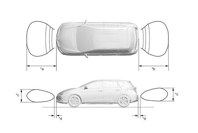
*a Approximately 1000 mm (39.4 in.) *b Approximately 1500 mm (59.1 in.) *c Approximately 650 mm (25.6 in.) *d Approximately 100 mm (3.9 in.) Figure 4. Center (Wagon Models)
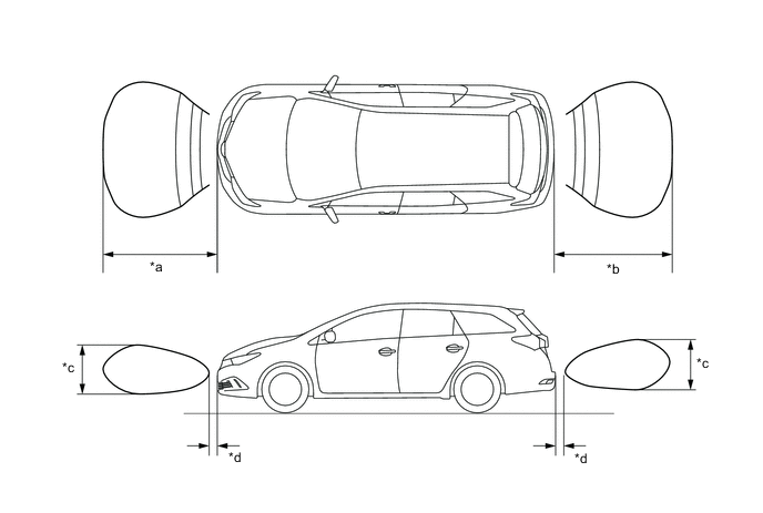
*a Approximately 1000 mm (39.4 in.) *b Approximately 1500 mm (59.1 in.) *c Approximately 650 mm (25.6 in.) *d Approximately 100 mm (3.9 in.) Figure 5. Sides (Hatchback Models)
*a Approximately 250 mm (9.8 in.) *b Approximately 400 mm (15.7 in.) *c Approximately 100 mm (3.9 in.) - - Figure 6. Sides (Wagon Models)
*a Approximately 250 mm (9.8 in.) *b Approximately 400 mm (15.7 in.) *c Approximately 100 mm (3.9 in.) - -
-
-
The operating condition of each sensor differs according to its installed position as shown in the table below:
Installation Position Operating Condition Front Corner
-
Ignition switch is ON.
-
System is activated.*1
-
Parking brake switch assembly is off.*2
-
Shift lever is in a position other than P.*3
-
Vehicle speed is approximately 10 km/h (6 mph) or less.
Front Center Front Side Rear Corner
-
Ignition switch is ON.
-
System is activated.*1
-
Back-up light switch is on.*2
-
Shift lever is in R.*3
Rear Center *1: Even if the back sonar or clearance sonar switch assembly is off, the system is activated when the simple-intelligent parking assist system is operating.
*2: Models with manual transaxle or multi-mode manual transaxle
*3: Models with multidrive/continuously variable transaxle
-
-
-
DIAGNOSIS
-
If a system malfunction is detected, the clearance warning ECU assembly stores Diagnostic Trouble Codes (DTCs) in its memory. For details, refer to the Repair Manual.
-