BRAKE SYSTEM
-
CONSTRUCTION
-
Brake Assist Mechanism
-
The brake assist mechanism consists of the slide valve, slide valve hook, air valve, control valve and valve operation rod in the brake booster assembly.
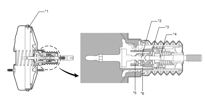
*1 Brake Booster Assembly *2 Air Valve *3 Control Valve *4 Valve Operation Rod *5 Slide Valve Hook *6 Slide Valve
-
-
-
OPERATION
-
Brake Assist Mechanism
-
When the brakes are not being applied, the air valve closes, and the pressure is the same in the variable pressure chamber and the constant pressure chamber.
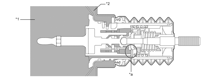
*1 Constant Pressure Chamber *2 Variable Pressure Chamber *a Air Valve Closed - - -
During normal braking, the air valve opens to activate the brake booster function.
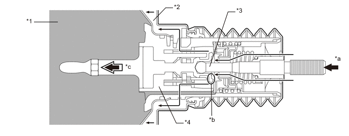
*1 Constant Pressure Chamber *2 Variable Pressure Chamber *3 Valve Operation Rod *4 Power Piston *a Push *b Air Valve Open *c Moves - - -
When the valve operation rod speed is faster than the power piston speed, the air valve pushes the slide valve hook. Consequently, the slide valve separates from the slide valve hook, and the slide valve pushes the control valve to open the air valve wider than under normal braking. Thus, the air volume that is introduced increases. This results in a brake assist force to powerfully push the power piston.
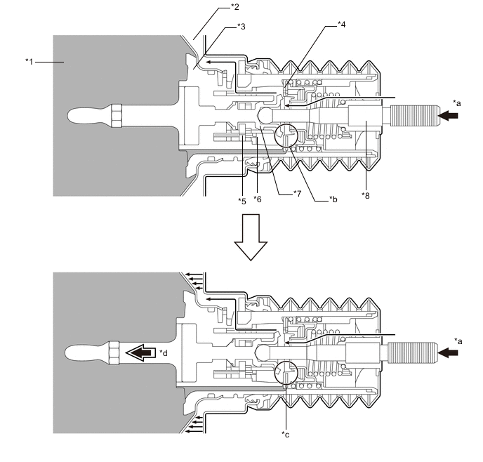
*1 Constant Pressure Chamber *2 Variable Pressure Chamber *3 Power Piston *4 Control Valve *5 Slide Valve Hook *6 Slide Valve *7 Air Valve *8 Valve Operation Rod *a Push *b Air Valve Open *c Air Valve "Wide Open" *d Moves a greater amount
-
-