CVT SYSTEM
-
FUNCTION OF MAIN COMPONENTS
Component Function Shift Solenoid Valve DS1 Controls the fluid flow volume to the primary pulley in accordance with the vehicle speed and accelerator pedal position (speed control during acceleration). Shift Solenoid Valve DS2 Shift Solenoid Valve DSU Controls the engagement oil pressure of the lock-up clutch. Shift Solenoid Valve SLT
-
Controls the line pressure.
-
Controls the engagement oil pressure of the forward clutch and reverse brake.
Shift Solenoid Valve SLS
-
Controls the oil pressure of the secondary pulley.
-
Controls the line pressure upon engagement of the forward clutch and reverse brake.
Transmission Revolution Sensor (NIN) Detects the primary pulley speed (input speed). Transmission Revolution Sensor (NOUT) Detects the secondary pulley speed (output speed). Transmission Revolution Sensor (NT) Detects the forward clutch drum speed. CVT Fluid Temperature Sensor Detects the CVT fluid temperature. Oil Pressure Sensor Detects the steel belt clamping force. E.F.I. Engine Coolant Temperature Sensor Detects the engine coolant temperature. Throttle Body Assembly Throttle Position Sensor Detects the opening angle of the throttle valve. Airbag Sensor Assembly Yawrate Sensor Detects the vehicle's inclined angle. Stop Light Switch Assembly Detects the brake pedal depressing signal. Park/Neutral Position Switch Assembly Detects the shift lever position. Shift Lock Control Unit Transmission Control Switch
-
Detects that the shift lever is in M.
-
Detects the driver's shift-up and shift-down operations when the shift lever is in M.
Shift Paddle Switch (Transmission Shift Switch)*1
-
Detects the driver's shift-up and shift-down operations in 7-speed sport sequential shiftmatic mode.
-
Operating this switch when the shift lever is in D changes the mode temporarily to 7-speed sport sequential shiftmatic mode.
Crank Position Sensor Detects the engine speed. Accelerator Pedal Sensor Detects the accelerator pedal opening angle. Brake Actuator Assembly Skid Control ECU
-
Transmits the vehicle speed and the longitudinal acceleration signal to the ECM.
-
Transmits the operating states of the ABS and VSC to the ECM.
Air Conditioning Amplifier Assembly*2 Transmits the operating state of the air conditioning system to the ECM. ECM Drives each solenoid valve based on signals from each sensor and switch and optimally controls the CVT. Combination Meter Assembly Shift Position and Shift Range Indicator Light Indicates the shift lever position. Malfunction Indicator Lamp (MIL) Illuminates or blinks to inform the driver when the ECM detects a malfunction. SPORT Mode Indicator Light Illuminates when SPORT mode is on. SPORT Mode Switch (Pattern Select Switch Assembly) Operating this switch turns SPORT mode on or off . *1: Models with shift paddle switch
*2: Models with air conditioning system
-
-
SYSTEM CONTROL
-
Control List
-
The electronic control system of the K311 CVT consists of the controls listed below.
Control Outline Engine - CVT Integrated Control Effects coordinate control of the CVT system and engine control system to ensure both smooth and powerful driving that excels in shift response and fuel economy. Automatic Shift Control (Speed Ratio Control) Controls the primary pulley speed to approach the target input rotation speed calculated based on the information such as the acceleration pedal opening angle, vehicle speed and brake signals. Acceleration Improvement Control Keeps the acceleration for the acceleration pedal opening angle to a certain level, improving the linearly acceleration feeling and expanding feeling for driver's accelerator pedal operation. Deceleration Improvement Control During deceleration, a pulley ratio is determined and high engine speed is maintained, thus ensuring adequate engine braking. Uphill/Downhill Shift Control Controls to restrict upshifts or to provide appropriate engine braking force by using the ECM to determine whether the vehicle is traveling on uphill or downhill. Lock-up Control Engages the lock-up clutch from low vehicle speeds to improve the fuel economy. 7-speed Sport Sequential Shiftmatic Enables driving in a gear step selected using the shift lever, providing engine braking force appropriate to each gear step.
-
-
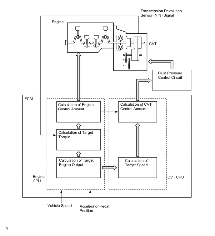
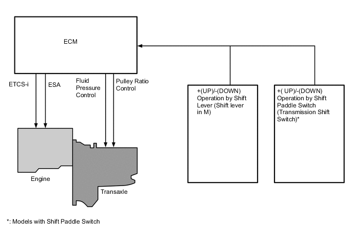
Engine - CVT Integrated Control
-
To effect fine-tuned control in accordance with driving conditions, various signals are exchanged between the engine control system and the CVT system. As a result, both smooth and powerful driving that excels in shift response and fuel economy has been achieved.
-
-
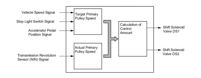
Automatic Shift Control (Speed Ratio Control)
-
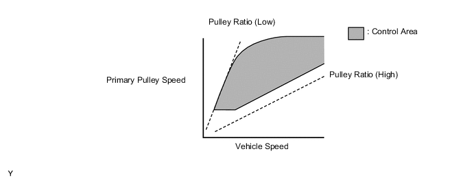
The ECM calculates the target primary pulley speed in accordance with the accelerator pedal position signal, vehicle speed signal, and stop light switch signal, in order to attain an optimal pulley ratio and shifting speed. To allow the actual primary pulley speed (acquired from the primary speed sensor) to match the target primary pulley speed, the ECM actuates shift solenoid valves DS1 and DS2 in order to control the pressure of primary pulley and secondary pulley. As a result, optimal pulley ratio and shifting speed have been achieved.
-
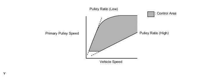
When the shift lever is in D, the system effects engine integrated control to optimize fuel economy characteristics and driving performance.
-
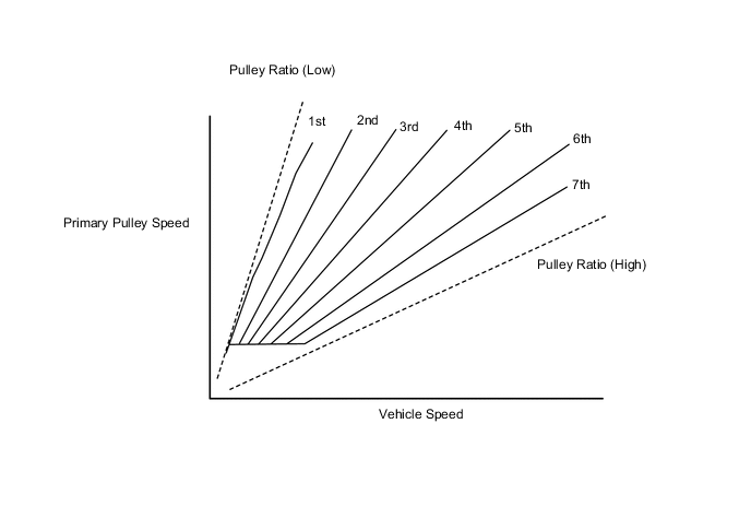
When the shift lever is in M, the shift characteristic is as shown below. The system will upshift automatically when the vehicle reaches the set speed during acceleration.
-
The sport mode limits the shift range for the acceleration side and maintains the primary pulley speed at high speeds. This produces a moderate engine braking force and provides an excellent shift response.
-
-
Acceleration Improvement Control
-
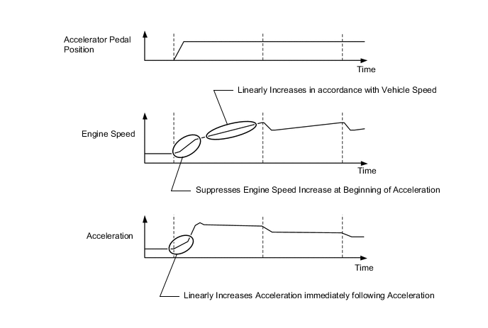
The system determines the driver's acceleration request based on the vehicle speed and the changes in the accelerator pedal position. When the system determines this request, it will change the shift characteristic into one in which the engine speed and vehicle speed increase linearly. This improves the acceleration feeling.
-
-
Deceleration Improvement Control
-
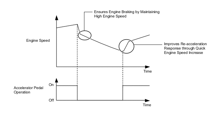
During deceleration, a pulley ratio is determined and high engine speed is maintained, thus ensuring adequate engine braking.
-
Engine control, which generates driving force quickly, is conducted during re-acceleration.
-
-
Uphill/Downhill Shift Control
-
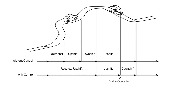
The uphill/downhill shift control helps shifting to an optimal speed ratio while driving on a winding uphill or downhill road.
-
When the ECM determines uphill travel, the control restricts upshifting, thus offering smooth driving.
-
If a signal indicating that the driver has operated the brake pedal is input while the ECM detects downhill travel, the control downshifts the speed ratio and generates an optimal engine braking force.
-
The actual acceleration calculated from the vehicle speed signal is compared with the reference acceleration (based on level road travel) stored in the ECM to determine uphill or downhill travel.
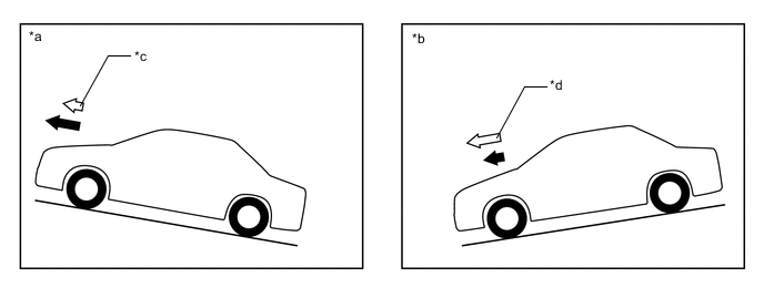
*a Uphill *b Downhill *c Smaller *d Greater 
Reference Acceleration 
Actual Acceleration
-
-
Lock-up Control
-
The ECM engages or disengages the lock-up clutch by activating the solenoid valve DSU based on the accelerator pedal opening angle and the vehicle speed.
-
The power transmission of the lock-up clutch (mechanical power transmission) and torque converter assembly (fluid power transmission) is controlled in accordance with the vehicle driving conditions, improving distribution efficiency. Additionally, enhancing the lock-up operation area to the low speed range enables the fuel cut area to be enhanced, achieving excellent fuel economy.
-
-
7-speed Sport Sequential Shiftmatic
-
The driver can select the desired gear step by moving the shift lever "+" (forward) or to "-" (backward) while the shift lever is in M (7-speed sport sequential shiftmatic mode). Thus, the driver is able to change gear steps with a manual-like feel.
-
A shift paddle switch (transmission shift switch), which enables the driver to perform shift operations while holding the steering wheel, is provided depending on the model.
-
7-speed sport sequential shiftmatic mode can be selected from normal driving mode by moving the shift lever to M. The driver can change the gear step by selecting it using the shift lever or shift paddle switch (transmission shift switch)*1. Engine braking force is provided in accordance with the selected gear step.*2
*1: Models with shift paddle switch
*2: On models with the shift paddle switch, if the shift paddle switch "+ (UP)" or "- (DOWN)" is operated during normal driving mode with the shift lever in D, gear step change operations are temporarily made available.
-
The shift position and shift range indicator light is provided in the multi-information display of the combination meter assembly. When the shift lever is in P, R, N or D, the shift position is indicated in the shift position and shift range indicator light. When the shift lever is in M, or temporary 7-speed sport sequential shiftmatic mode is selected with the shift lever in D*, "M" or "D" and the selected shift range is displayed in the shift position and shift range indicator light.
*: Models with shift paddle switch
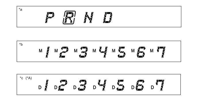
*A Models with Shift Paddle Switch - - *a When shift lever is in P, R, N or D *b When shift lever is in M *c During temporary 7-speed sport sequential shiftmatic mode with shift lever in D - - -
In M mode, the transmission automatically upshifts or downshifts under the following conditions:
Condition System Control Engine is under-revving. 1 step downshift Engine is over-revving. 1 step upshift -
When the vehicle is stopped during temporary 7-speed sport sequential shiftmatic mode, the transmission automatically downshifts to M1.
-
The ECM will restrict the changing of the shift range if it detects a malfunction in the CVT system.
-
If the vehicle speed and engine speed exceeds or goes below a preset level in response to the driver's downshift operation request, changing the shift range will be prohibited. In this case, the buzzer in the combination meter will sound to alert the driver.
-
-
-
FAIL-SAFE
-
This fail-safe function minimizes the loss of operability when an abnormality occurs in a sensor or shift solenoid valve. For details, refer to the Repair Manual.
-
-
DIAGNOSIS
-
When the ECM detects a malfunction, the ECM records the malfunction and memorizes the information related to the fault. Furthermore, the ECM illuminates or blinks the Malfunction Indicator Lamp (MIL) in the combination meter assembly to inform the driver.
-
The ECM will also store the Diagnostic Trouble Codes (DTCs) of the malfunctions. The DTCs stored in the ECM are output to the Global TechStream (GTS) via the ECM and the DLC3. For details, refer to the Repair Manual.
Tech Tips
To clear a DTC that is stored in the ECM, use the Global TechStream (GTS) or disconnect the cable from the battery terminal for 1 minute or longer.
-