STOP AND START
-
CONSTRUCTION
-
In this permanently engaged gear mechanism, the bearing, ERS 1way clutch assembly, and ERS ring gear sub-assembly are positioned between the crankshaft and flywheel sub-assembly, allowing the pinion gear of the starter assembly and the ERS ring gear sub-assembly to be continuously engaged.
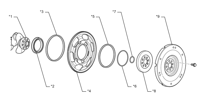
*1 Crankshaft *2 Bearing *3 Outer Oil Seal *4 ERS Ring Gear Sub-assembly *5 Inner Oil Seal *6 Snap Ring *7 O-ring *8 ERS 1Way Clutch Assembly *9 Flywheel Sub-assembly - - -
When the engine is being started or restarted, the starter assembly starts operating and the ERS ring gear sub-assembly rotates. The inner race of the ERS ring gear sub-assembly pushes the sprags against the outer race, locking the ERS ring gear sub-assembly to the crankshaft, thus turning the crankshaft and starting the engine.
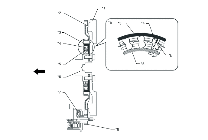
*1 Flywheel Sub-assembly *2 ERS Ring Gear Sub-assembly *3 Outer Race (ERS 1Way Clutch Assembly) *4 Sprag *5 Inner Race (ERS 1Way Clutch Assembly) *6 Crankshaft *7 Starter Assembly *8 Pinion Gear *a Front-view *b Torque Transmission 
Engine Front 
Rotation Direction -
After the engine has started, the crankshaft starts turning faster than the ERS ring gear sub-assembly. When this happens, the sprags of the ERS 1way clutch assembly are released and the ERS ring gear sub-assembly and the crankshaft are unlocked. If the starter stops, the ERS ring gear sub-assembly also stops.
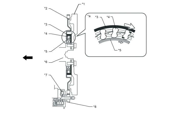
*1 Flywheel Sub-assembly *2 ERS Ring Gear Sub-assembly *3 Outer Race (ERS 1Way Clutch Assembly) *4 Sprag *5 Inner Race (ERS 1Way Clutch Assembly) *6 Crankshaft *7 Starter Assembly *8 Pinion Gear *a Front-view - - Engine Front Rotation Direction
-