EMISSION CONTROL SYSTEM
-
FUNCTION OF MAIN COMPONENTS
-
The main components of the 1AD-FTV emission control system are as follows:
Components Outline Quantity Function Differential Pressure Sensor Semiconductor Strain Gauge Type 1 This pressure sensor measures the pressure differences between the front and back of the DPF catalyst with PM in order to detect the clogging. Exhaust Gas Temperature Sensor Thermistor Type 3 The exhaust gas temperature sensor is installed in the front and back of the oxidation catalyst and back of the DPF catalyst in order to detect the temperature of the exhaust gas. Exhaust Fuel Addition Injector Solenoid Type 1 The injector injects fuel into the exhaust port. Air Fuel Ratio Sensor Heated Type (Planar Type) 1 This sensor detects the oxygen concentration in the exhaust gas. DPF Catalytic Converter (Exhaust Manifold Converter Sub-assembly) On Exhaust Pipe Front 1 This converter traps PM in the exhaust gas and further oxidizes CO and HC to purify and convert them into CO2and H2O.
EGR Cooler Assembly Water-cooled Type 1 The EGR cooler cools the exhaust gas temperature to improve the EGR efficiency, thus reducing NOXin the exhaust gas.
EGR Cooler Bypass Switching Valve VSV Drive Type 1 This valve opens and closes to control the EGR cooler bypass amount in accordance with the engine operating conditions. EGR Valve DC Motor Drive Type 1 This valve opens and closes in accordance with the engine operating conditions and optimally controls the EGR amount. EGR Valve Position Sensor Contact Type 1 This sensor detects the actual amount of the EGR valve opening.
-
-
SYSTEM CONTROL
-
System Control Table
-
The emission control system of the 1AD-FTV engine has the following systems.
System Outline EGR Control Based on the signals received from the sensors, the ECM determines the EGR volume via the EGR valve and throttle valve in accordance with the engine condition. Catalyst Support Control Based on the signals received from the sensors, the ECM controls the fuel injection timing, injection frequency and the engine idle speed to purify PM. Air Fuel Ratio Sensor Heater Control Maintains the temperature of the air fuel ratio sensor at an appropriate level to increase accuracy of detection of the oxygen concentration in the exhaust gas.
-
-
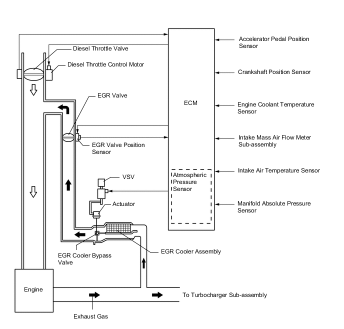
EGR Control
-
This system is designed to reduce and control NOx formation due to a reduction of peak temperature in the engine combustion chamber, which is accomplished by introducing the exhaust gas into the intake manifold.
-
By sensing the engine driving conditions and actual amount of the EGR valve opening, the ECM operates the EGR valve and diesel throttle control motor, and regulates the amount of exhaust gas.
-
-
Catalyst Support Control
-
If the DPF catalyst temperature becomes low, catalyst performance decreases, resulting in an increase of the amount of PM stuck in the filter substrate. The ECM detects that the filter substrate is clogged by calculating the accumulated volume of the PM discharged by the engine. To reduce PM, the ECM controls the injection timing and the injection frequency of the injectors, and activates the exhaust fuel addition injector.
-
At the same time, the filter substrate temperature becomes high and PM reacts with active oxygen and changes into CO2 for purification.
-
Fuel efficiency drops while this control is operative.
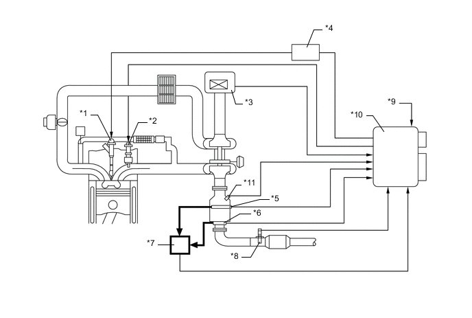
*1 Injector Assembly *2 Exhaust Fuel Addition Injector *3 Intake Mass Air Flow Meter Sub-assembly *4 Injector Driver *5 No. 2 Exhaust Gas Temperature Sensor *6 No.3 Exhaust Gas Temperature Sensor *7 Differential Pressure Sensor *8 Air Fuel Ratio Sensor *9 Engine Coolant Temperature Sensor *10 ECM *11 Exhaust Gas Temperature Sensor - - Tech Tips
-
When replacing the exhaust manifold converter with a new one, it is necessary to perform initialization of the DPF catalyst deteriorate data history in the ECM by using a Global TechStream (GTS).
-
When replacing the ECM with a new one, it is necessary to read DPF catalyst deteriorate data history from the installed ECM and then transfer that data history to the new ECM by using a Global TechStream (GTS). When the DPF catalyst deteriorate data history is not transferred, Diagnostic Trouble Code (DTC) P1601 is stored in the ECM, and the Malfunctioning Indicator Lamp (MIL) comes on.
-
When replacing both the exhaust manifold converter and the ECM, it is necessary to perform initialization of the DPF catalyst deteriorate data history in the ECM using a Global TechStream (GTS). When DPF catalyst deteriorate history initialization is not performed, DTC P1601 is stored in the ECM and the Malfunctioning Indicator Lamp (MIL) comes on.
-
-
-