FUEL SYSTEM
-
CONSTRUCTION
-
The supply pump (injection or supply pump assembly) consists of an inner cam (eccentric camshaft), an outer cam (polygon ring), 3 plungers, a metering unit and a gear pump. Each plunger is placed outside of the outer cam.
-
The gear pump pumps fuel to the 3 plungers.
-
A metering unit controls the volume of fuel drawn into the plungers.
-
The inner cam drives the outer cam.
-
The outer cam drives the 3 plungers.
-
The plungers pressurize the fuel.
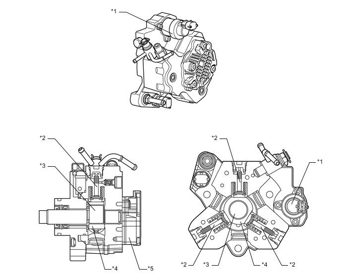
*1 Metering Unit *2 Plunger *3 Inner Cam (Eccentric Camshaft) *4 Outer Cam *5 Gear Pump - -
-
-
OPERATION
-
Due to the rotation of the inner cam (eccentric camshaft), the outer cam pushes plunger "A" upward as illustrated below. The force of the spring pulls plunger "B". As a result, plunger "B" draws fuel in, and plunger "A" pumps fuel at the same time.
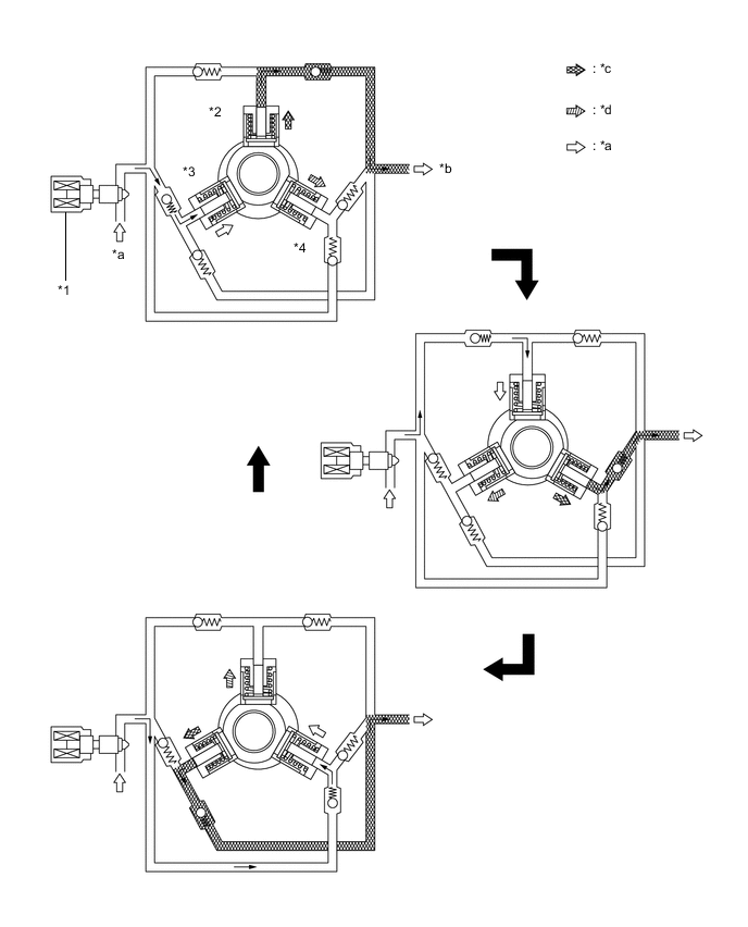
*1 Metering Unit *2 Plunger A *3 Plunger B *4 Plunger C *a Suction *b to Common-rail *c Pumping Finish *d Pumping Start
-