ENGINE UNIT
-
CONSTRUCTION
-
The intake side valve mechanism utilizes a VALVEMATIC mechanism. The VALVEMATIC mechanisms are operated by the continuously variable valve lift controller assembly.
-
The cam on the camshaft pushes the roller arm, causing the oscillating cam to rotate in the same direction as the roller arm. Then, the oscillating cam pushes on the No. 1 valve rocker arm sub-assembly, opening the intake valve.
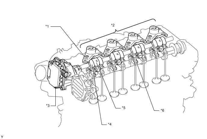
*1 Valve Rocker Arm Lost Motion Damper Sub-assembly *2 VALVEMATIC Mechanism *3 Continuously Variable Valve Lift Controller Assembly *4 Oscillating Cam *5 Roller Arm *6 No. 1 Valve Rocker Arm Sub-assembly -
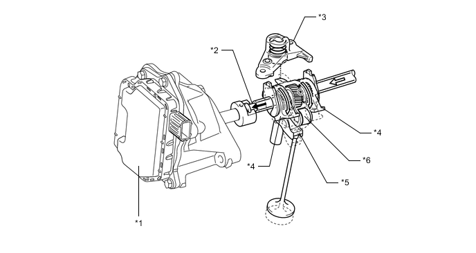
The control shaft transmits the linear movement of the continuously variable valve lift controller assembly to the slider located inward of the roller arm and oscillating cam. Because the roller arm is held in place by the valve rocker arm lost motion damper sub-assembly, the slider's helical splines and the helical splines inside the roller arm cause the slider to rotate. As a result, the slider rotates the oscillating cam. The rotation of the oscillating cam varies continuously in order to continuously vary the amount of intake valve lift and the intake valve action angle.
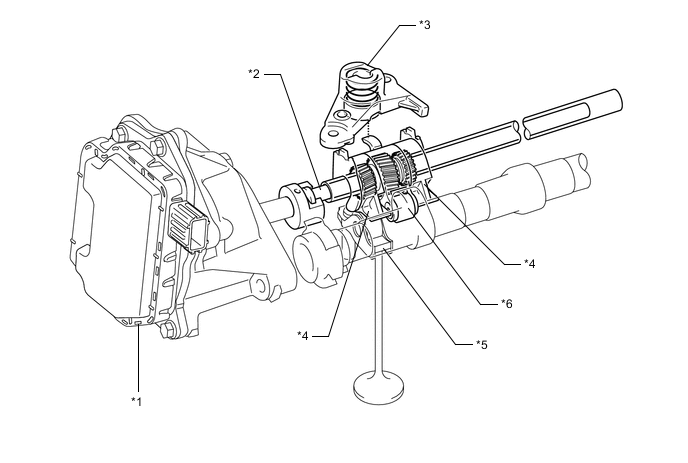
*1 Continuously Variable Valve Lift Controller Assembly *2 Control Shaft *3 Valve Rocker Arm Lost Motion Damper Sub-assembly *4 Oscillating Cam *5 No. 1 Valve Rocker Arm Sub-assembly *6 Roller Arm -
As the continuously variable valve lift controller assembly pushes on the control shaft, the oscillating cam rotates counterclockwise as seen from the continuously variable valve lift controller assembly. As a result, the pressure exerted on the No. 1 valve rocker arm sub-assembly decreases, thus reducing the amount of valve lift.
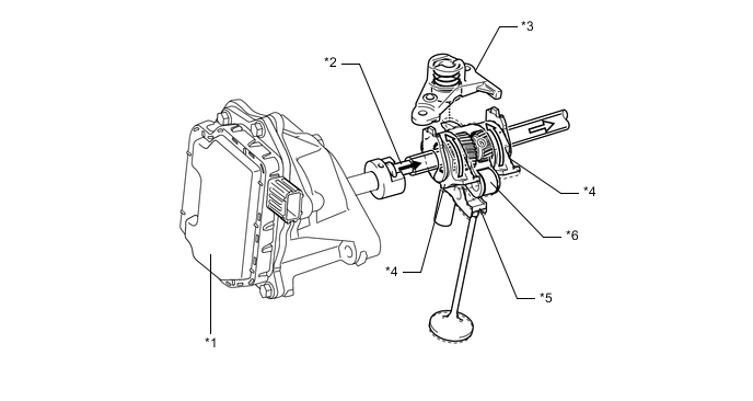
*1 Continuously Variable Valve Lift Controller Assembly *2 Control Shaft *3 Valve Rocker Arm Lost Motion Damper Sub-assembly *4 Oscillating Cam *5 No. 1 Valve Rocker Arm Sub-assembly *6 Roller Arm 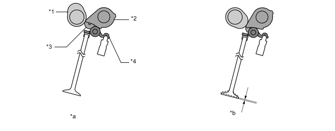
*1 Cam *2 Oscillating Cam *3 Roller Arm *4 No. 1 Valve Rocker Arm Sub-assembly *a Initial Position *b Minimum Amount of Valve Lift -
As the continuously variable valve lift controller assembly pulls on the control shaft, the oscillating cam rotates clockwise as seen from the continuously variable valve lift controller assembly. As a result, the pressure exerted on the No. 1 valve rocker arm sub-assembly increases, thus increasing the amount of valve lift.
*1 Continuously Variable Valve Lift Controller Assembly *2 Control Shaft *3 Valve Rocker Arm Lost Motion Damper Sub-assembly *4 Oscillating Cam *5 No. 1 Valve Rocker Arm Sub-assembly *6 Roller Arm 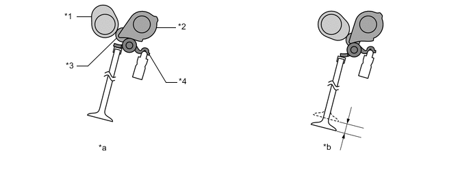
*1 Cam *2 Oscillating Cam *3 Roller Arm *4 No. 1 Valve Rocker Arm Sub-assembly *a Initial Position *b Maximum Amount of Valve Lift
-