ENGINE UNIT
-
CONSTRUCTION
-
The ventilation inside the stiffening crankcase assembly uses the same PCV valve (ventilation valve sub-assembly) as a Natural Aspiration (NA) engine. In addition, blow-by gas ventilation control, which forcibly performs ventilation when in the supercharging range by using an ejector, is used. As a result, blow-by gas with a hydrocarbons is prevented from being discharged into the atmosphere by forcibly introducing the blow-by gas into the intake system and combusting the gas. Also, the same oil maintenance schedule as an NA engine is achieved by actively performing ventilation during all driving ranges.
-
As turbocharged engines produce more blow-by gas than NA engines, an oil separator chamber is installed to the engine block sub-assembly to provide adequate length for the blow-by gas passage. As a result, the efficiency of separating engine oil from the blow-by gas is enhanced.
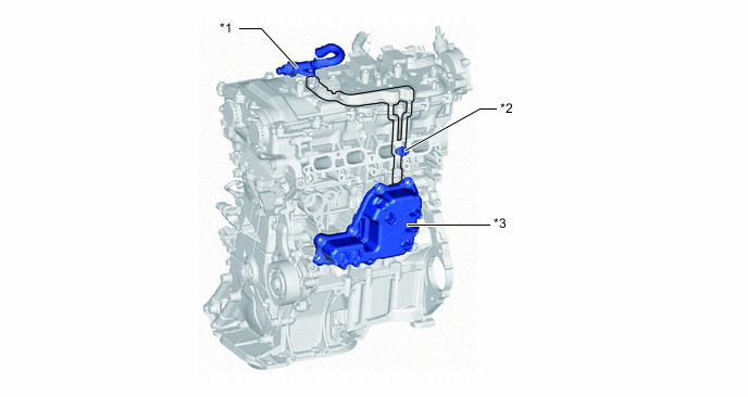
*1 Ejector *2 PCV Valve (Ventilation Valve Sub-assembly) *3 Oil Separate Chamber - -
-
-
OPERATION
-
When operating in the turbocharged range, blow-by gas is forcibly routed through the intake air duct by the ejector.
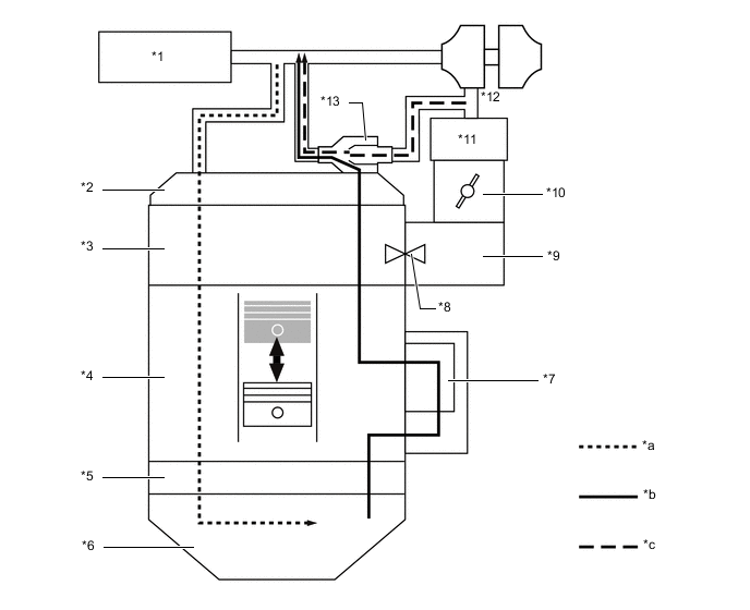
*1 Air Cleaner Assembly *2 Cylinder Head Cover Sub-assembly *3 Cylinder Head Sub-assembly *4 Cylinder Block Sub-assembly *5 Stiffening Crankcase Assembly *6 Oil Pan Sub-assembly *7 Oil Separate Chamber *8 PCV Valve (Ventilation Valve Sub-assembly) *9 Intake Manifold *10 Throttle Body Assembly *11 Intercooler Assembly *12 Turbocharger Sub-assembly *13 Ejector - - *a Fresh Air *b Fresh Air + Blowby Gas *c Ejector Drive Gas - - -
When operating in the natural aspirated range, blow-by gas is suctioned via the PCV valve (ventilation valve sub-assembly) due to the vacuum in the intake air ducts.
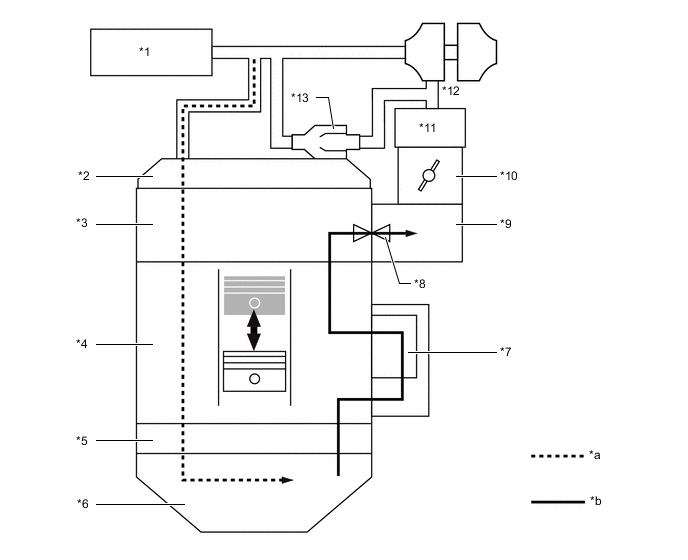
*1 Air Cleaner Assembly *2 Cylinder Head Cover Sub-assembly *3 Cylinder Head Sub-assembly *4 Cylinder Block Sub-assembly *5 Stiffening Crankcase Assembly *6 Oil Pan Sub-assembly *7 Oil Separate Chamber *8 PCV Valve (Ventilation Valve Sub-assembly) *9 Intake Manifold *10 Throttle Body Assembly *11 Intercooler Assembly *12 Turbocharger Sub-assembly *13 Ejector - - *a Fresh Air *b Fresh Air + Blowby Gas -
The ejector uses the Venturi effect as its operating principle. Blow-by gas is drawn in by introducing the high pressure air to the ejector.
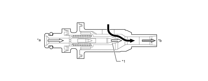
*1 Nozzle - - *a From Downstream of Turbocharger Sub-assembly *b Towards Upstream of Turbocharger Sub-assembly 
Blowby Gas 
Drive Gas 
Blowby Gas + Drive Gas - -
-