ENGINE UNIT
-
CONSTRUCTION
-
An aluminum cylinder block sub-assembly with a 7 mm (0.276 in.) distance between the cylinder bores is used to achieve a compact and lightweight configuration.
-
An oil separator is provided in the blow-by gas passage inside the cylinder block sub-assembly. This separates the engine oil from the blow-by gas in order to reduce the degradation and consumption of volume of the engine oil.
-
A spiny type liner, which has an irregularly shaped outer casting surface, is used to enhance the adhesion between the liners and the aluminum of the cylinder block sub-assembly. The enhanced adhesion helps heat dissipation, resulting in a lower overall temperature and reduced heat deformation of the cylinder bores. A cylinder block sub-assembly with this type of liner cannot be rebored.
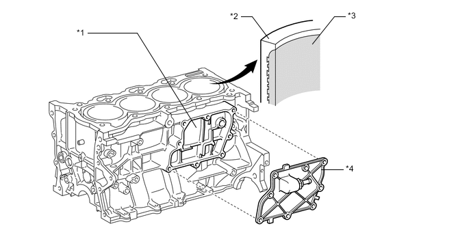
*1 Oil Separator *2 Cylinder Block Sub-assembly *3 Spiny Type Liner (Irregularly shaped outer casting surface of liner) *4 No. 1 Ventilation Case (Oil Separator Cover) -
Through the use of an offset crankshaft, the centerline of the cylinder bores is shifted 8 mm (0.315 in.) towards the intake in relation to the crankshaft center. Thus, the side force (thrust) applied to the cylinder walls is reduced when maximum combustion pressure is applied, which contributes to fuel economy.
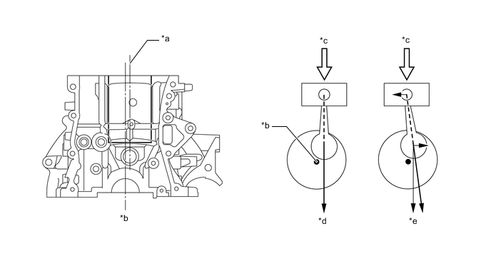
*a Bore Centerline *b Crankshaft Centerline *c Maximum Pressure *d Offset Crankshaft *e Non-offset Crankshaft - -
-