ENGINE UNIT
-
CONSTRUCTION
-
A VVT-i controller (camshaft timing gear assembly or camshaft timing exhaust gear assembly) consists of a housing driven by the chain sub-assembly and a vane coupled with the intake camshaft (camshaft) or exhaust camshaft (No. 2 camshaft).
-
Both the camshaft timing gear assembly and camshaft timing exhaust gear assembly have a 4-blade vane.
-
The oil pressure sent from the advanced or retarded side path at the intake camshaft (camshaft) and exhaust camshaft (No. 2 camshaft) causes rotation in a camshaft timing gear assembly vane circumferential direction to vary the intake and exhaust valve timing continuously.
-
When the engine is stopped, a lock pin locks the intake camshaft (camshaft) at its most retarded position and the exhaust camshaft (No. 2 camshaft) at its most advanced position, to ensure that the engine starts properly.
-
An advance assist spring is provided on the exhaust side camshaft timing gear assembly. This spring applies torque in the advance direction when the engine is stopped, thus ensuring the engagement of the lock pin.
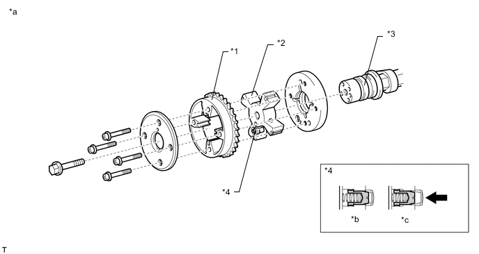
*1 Housing *2 Vane (Fixed on Intake Camshaft) *3 Intake Camshaft (Camshaft) *4 Lock Pin *a Intake VVT-i Controller (Camshaft Timing Gear Assembly) *b Engine Stopped *c Engine Operating - - 
Oil Pressure - - 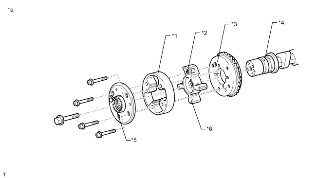
*1 Housing *2 Lock Pin *3 Sprocket *4 Exhaust Camshaft (No. 2 Camshaft) *5 Advance Assist Spring *6 Vane (Fixed on Exhaust Camshaft) *a Exhaust VVT-i Controller (Camshaft Timing Exhaust Gear Assembly) - -
-