ENGINE UNIT
-
CONSTRUCTION
-
An aluminum cylinder block sub-assembly with a 7 mm (0.276 in.) distance between the cylinder bores is used to achieve a compact and lightweight configuration.
-
A spiny type liner, which has an irregularly shaped outer casting surface, is used to enhance the adhesion between the liners and the aluminum of the cylinder block sub-assembly. The enhanced adhesion helps heat dissipation, resulting in a lower overall temperature and reduced heat deformation of the cylinder bores. A cylinder block sub-assembly with this type of liner cannot be rebored.
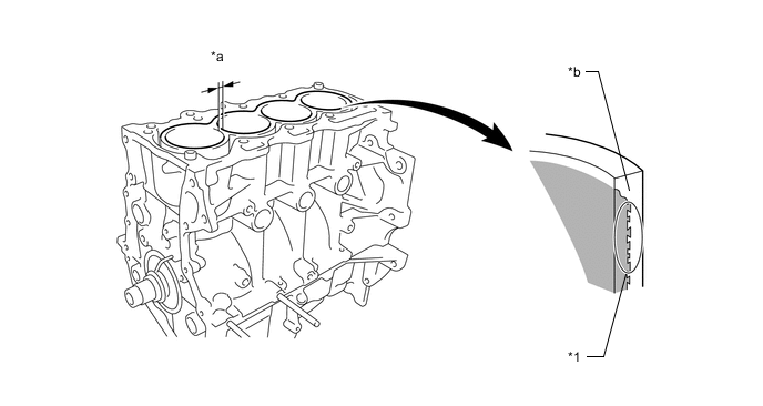
*1 Spiny Type Liner - - *a 7 mm (0.276 in.) *b Irregularly Shaped Outer Casting Surface of Liner -
Through the use of an offset crankshaft, the centerline of the cylinder bores is shifted 8 mm (0.315 in.) towards the exhaust in relation to the centerline of the crankshaft. Thus, the side force (thrust) applied to the cylinder walls is reduced when maximum combustion pressure is applied. This contributes to fuel economy.
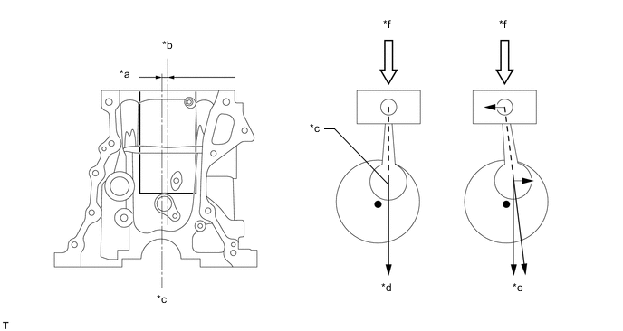
*a 8 mm (0.315 in) *b Bore Centerline *c Crankshaft Centerline *d Offset Crankshaft *e Non-offset Crankshaft *f Maximum Pressure -
A cylinder block water jacket spacer is provided in the cylinder block sub-assembly.
-
The cylinder block water jacket spacer suppresses the water flow in the center of the water jackets, guides the coolant above and below the cylinder bores, and ensures uniform temperature distribution. As a result, the viscosity of the engine oil that acts as a lubricant between the bore walls and the pistons can be lowered, thus reducing friction.
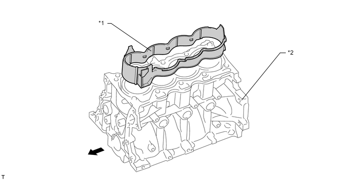
*1 Cylinder Block Water Jacket Spacer *2 Cylinder Block Sub-assembly 
Engine Front - -
-