SFI SYSTEM
Figure 1. Hatchback and Wagon Models
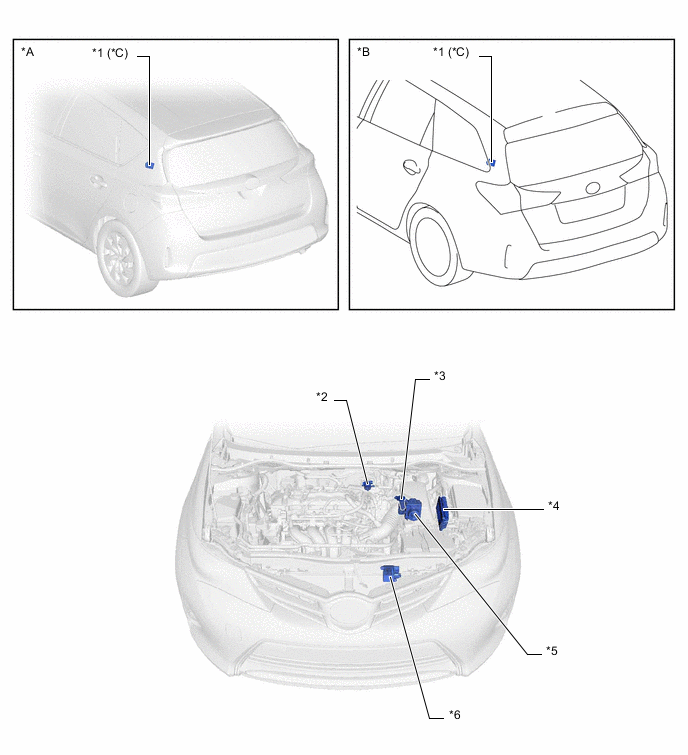
| *A | Hatchback Models | *B | Wagon Models |
| *C | EURO V Models | - | - |
| *1 | Fuel Pump Control ECU Assembly | *2 | Purge VSV |
| *3 | Intake Mass Air Flow Meter Sub-assembly
|
*4 | ECM |
| *5 | Brake Actuator Assembly
|
*6 | Cooling Fan ECU |
Figure 2. Sedan Models
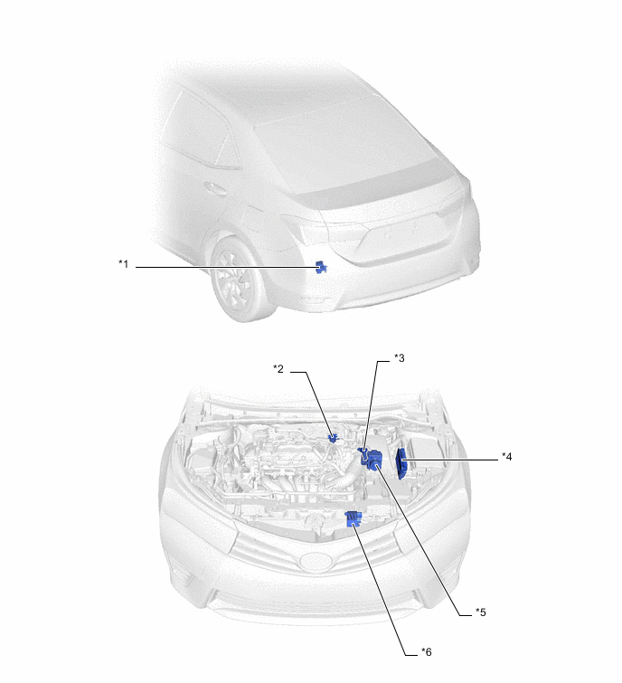
| *1 | Fuel Pump Control ECU Assembly | *2 | Purge VSV |
| *3 | Intake Mass Air Flow Meter Sub-assembly
|
*4 | ECM |
| *5 | Brake Actuator Assembly
|
*6 | Cooling Fan ECU |
Figure 3. LHD Models
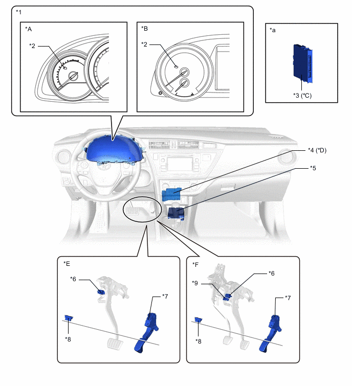
| *A | Models with Segment LCD Type Multi-information Display | *B | Models with Dot LCD Type Multi-information Display |
| *C | Models with Entry and Start System | *D | Models with Air Conditioning System |
| *E | Models with Multidrive/Continuously Variable Transaxle | *F | Models with Manual Transaxle |
| *1 | Combination Meter Assembly | *2 | Malfunction Indicator Lamp (MIL) |
| *3 | Certification ECU (Smart Key ECU Assembly) | *4 | Air Conditioning Amplifier Assembly |
| *5 | Airbag Sensor Assembly | *6 | Stop Light Switch Assembly |
| *7 | Accelerator Pedal Sensor Assembly | *8 | DLC3 |
| *9 | Clutch Start Switch Assembly | - | - |
| *a | Refer to the Service Bulletin for the installation position of the part. | - | - |
Figure 4. RHD Models
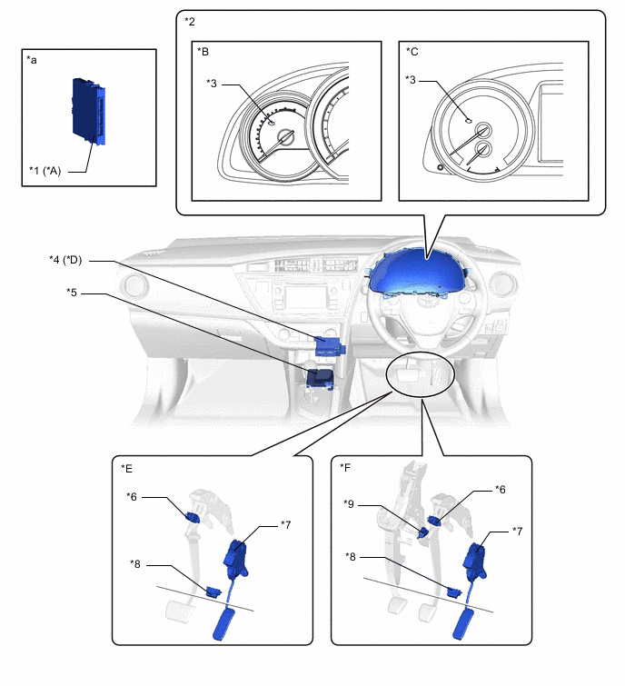
| *A | Models with Entry and Start System | *B | Models with Segment LCD Type Multi-information Display |
| *C | Models with Dot LCD Type Multi-information Display | *D | Models with Air Conditioning System |
| *E | Models with Multidrive/Continuously Variable Transaxle | *F | Models with Manual Transaxle |
| *1 | Certification ECU (Smart Key ECU Assembly) | *2 | Combination Meter Assembly |
| *3 | Malfunction Indicator Lamp (MIL) | *4 | Air Conditioning Amplifier Assembly |
| *5 | Airbag Sensor Assembly | *6 | Stop Light Switch Assembly |
| *7 | Accelerator Pedal Sensor Assembly | *8 | DLC3 |
| *9 | Clutch Start Switch Assembly | - | - |
| *a | Refer to the Service Bulletin for the installation position of the part. | - | - |
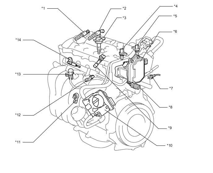
| *1 | Camshaft Timing Oil Control Valve Assembly (Intake) | *2 | Camshaft Timing Oil Control Valve Assembly (Exhaust) |
| *3 | Ignition Coil Assembly | *4 | Cam Position Sensor (No. 1 Crank Position Sensor) (Intake) |
| *5 | Cam Position Sensor (No. 1 Crank Position Sensor) (Exhaust) | *6 | Continuously Variable Valve Lift Controller Assembly |
| *7 | Air Fuel Ratio Sensor | *8 | E. F. I. Engine Coolant Temperature Sensor |
| *9 | Crank Position Sensor | *10 | Throttle Body Assembly
|
| *11 | Knock Control Sensor | *12 | E. F. I. Vacuum Sensor Assembly |
| *13 | Duty Vacuum Switching Valve | *14 | Fuel Injector Assembly |
Figure 5. Hatchback and Wagon Models
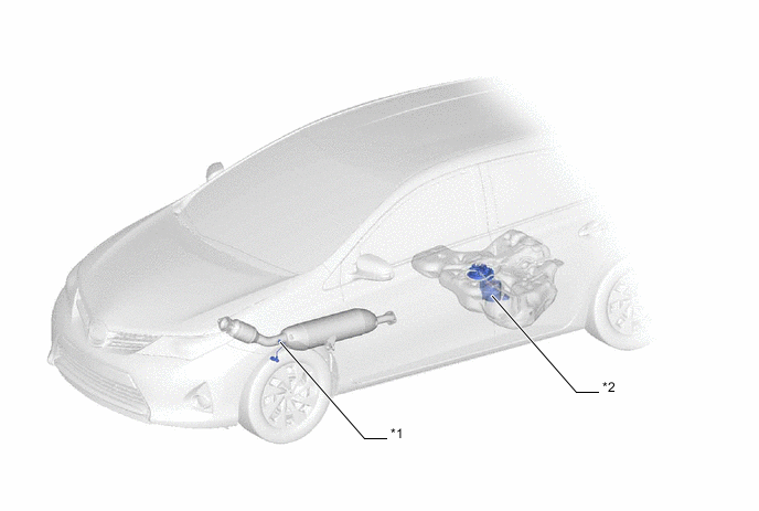
| *1 | Oxygen Sensor | *2 | Fuel Suction Tube with Pump and Gauge Assembly |
Figure 6. Sedan Models
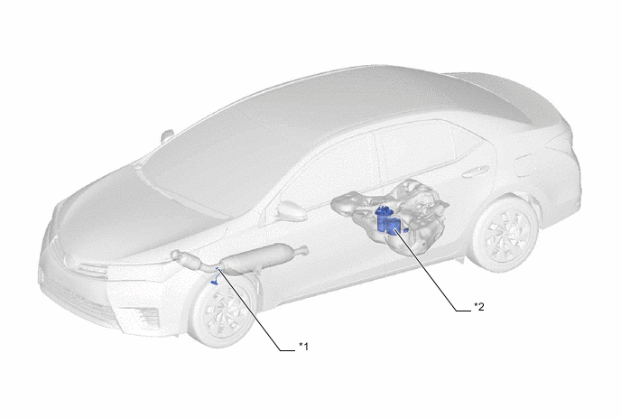
| *1 | Oxygen Sensor | *2 | Fuel Suction Tube with Pump and Gauge Assembly |