SFI SYSTEM
-
CONSTRUCTION
-
Magnetic Resistance Element (MRE) type sensors are used for the crank position sensor, cam position sensor (No. 1 crank position sensor) (intake) and cam position sensor (No. 1 crank position sensor) (exhaust).
-
The timing rotor of the crankshaft has 34 teeth, with 2 teeth missing. Based on these teeth, the crank position sensor transmits crank position signals (NE signal) consisting of 33 high or low output pulses every 10° per revolution of the crankshaft. The ECM uses the NE signal for detecting the crank position as well as for detecting the engine speed. It uses the missing teeth signal for determining the top dead center.
-
To detect the cam position, each timing rotor on the intake and exhaust camshafts is used to generate 6 (3 high output, 3 low output) pulses for every 2 revolutions of the crankshaft.
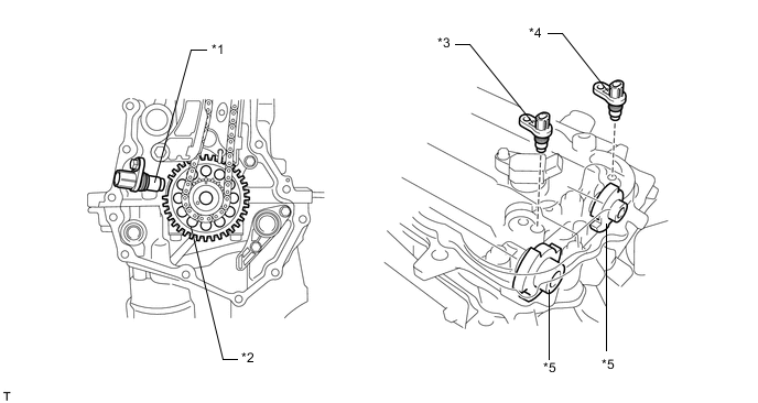
*1 Crank Position Sensor *2 Timing Sprocket *3 Cam Position Sensor (No. 1 Crank Position Sensor) (Exhaust) *4 Cam Position Sensor (No. 1 Crank Position Sensor) (Intake) *5 Timing Rotor - - 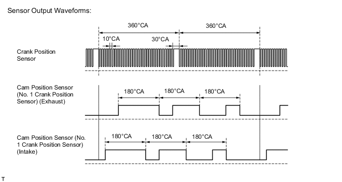
-
An MRE type sensor consists of an MRE, a magnet and a sensor. The direction of the magnetic field changes due to the profile (protruding and non-protruding portions) of the timing rotor, which passes by the sensor. As a result, the resistance of the MRE changes, and the output voltage to the ECM changes to either high or low. The ECM detects the crank position and intake and exhaust cam positions based on this output voltage.
-
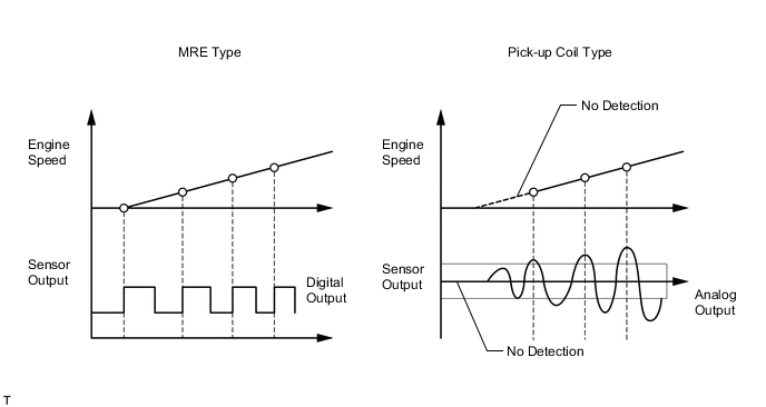
The differences between an MRE type sensor and the pick-up coil type sensor used on a conventional model are as follows.
-
An MRE type sensor outputs a constant level of high/low digital signals regardless of the engine speed. Therefore, an MRE type sensor can detect the positions of the crankshaft and camshaft at an early stage of cranking.
-
A pickup coil type sensor outputs analog signals with levels that change with engine speed.
-
-
In order to deliver a smooth engine restart from the engine stop state, the MRE type crank position sensor provided on models with the stop and start system detects crankshaft movements swinging back and forth from the timing rotor rotation direction when the engine has been brought into a stop, helping the ECM determine a more exact crankshaft stop position.
-
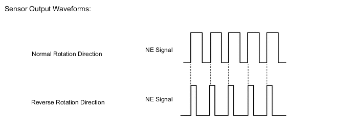
The MRE type crank position sensor determines the timing rotor rotation direction from the phase difference between the 2 rectangular wave signals generated by the sensor itself, and then transmits Hi/Lo signals, a short low voltage time when the timing rotor rotates in the normal direction and a long low voltage time when in the reverse direction, to the ECM.
-