METER / GAUGE SYSTEM GENERAL
-
OUTLINE
-
Combination Meter Assembly
-
A combination meter assembly, which has a color type multi-information display, is provided.
-
The combination meter assembly has a built-in meter ECU and a buzzer.
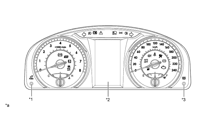
Text in Illustration (Except TMMK Made Models:) *1 Rheostat Switch *2 Multi-information Display *3 ODO/TRIP Switch - - *a The illustration shown is an example only. - - 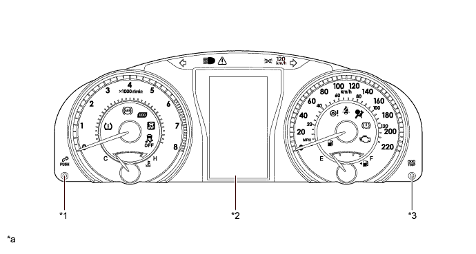
Text in Illustration (TMMK Made Models:) *1 Rheostat Switch *2 Multi-information Display *3 ODO/TRIP Switch - - *a The illustration shown is an example only. - -
-
-
-
MAJOR DIFFERENCE
-
The new models have been modified from the previous models as shown below:
-
A tire pressure warning light has been added (TMMK made models).
-
-
-
MAIN FEATURES
-
Opening/Ending Ceremony (Except TMMK Made Models)
-
An opening/ending ceremony which allows for anticipation of a pleasant drive is used. The ceremony operates as follows:
-
When the ignition switch is turned to ON, the needles, gauges and panels of the speedometer, tachometer, engine coolant temperature gauge and fuel gauge and the multi-information display illuminate.
-
When the ignition switch is turned off, all the illuminations fade out. During this period, the multi-information display shows the Eco Drive Level for 3 seconds.
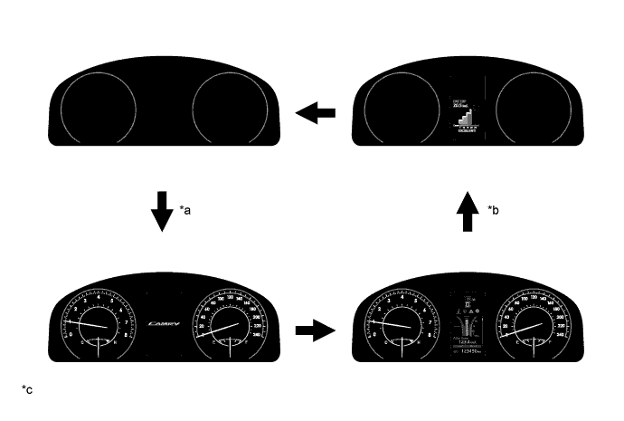
Text in Illustration *a IG ON *b IG OFF *c The illustrations shown are examples only. - -
-
-
-
Opening/Ending Ceremony (TMMK Made Models)
-
An opening/ending ceremony which allows for anticipation of a pleasant drive is used. The ceremony operates as follows:
-
When the engine switch is turned on (IG), the needles of the speedometer, tachometer, engine coolant temperature gauge and fuel gauge illuminate.
-
Then, the gauges and panels of the speedometer, tachometer, engine coolant temperature gauge and fuel gauge and the multi-information display illuminate.
-
When the engine switch is turned off, all the illuminations fade out. During this period, the multi-information display shows the Trip Summary for 3 seconds.
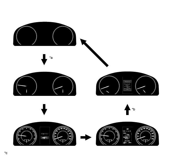
Text in Illustration *a IG ON *b IG OFF *c The illustrations shown are examples only. - -
-
-
-
Multi-information Display
-
The multi-information display is located at the center of the combination meter assembly.
-
The multi-information display shows the following information.
Item Outline Shift Position Indicator The current shift position is displayed. Outside Temperature
-
The outside temperature is displayed.
-
When the outside temperature drops below 3°C (37°F), an ice warning light illuminates to warn the driver to drive with caution due to possibly icy road conditions. After the ice warning light flashes 10 times, the light stays on. When the temperature reaches 5°C (41°F), the light goes off.
Indicator When the display conditions are met, the following indicators illuminate.
-
Cruise Control Indicator*1
-
Cruise SET Indicator*1
Information The following information can be displayed on the multi-information display by switching the tabs.
-
Drive Information
-
Navigation Information*2
-
Cruise Control System Information*3
-
Warning Message
-
Settings
Tech Tips
The tab can be switched using the RIGHT (PAGE) switch of the steering pad switch assembly.
Operation Guide*3 When the cruise control system is operated, the operation result is displayed. Vehicle Power Source State*3 Smart Indicator is displayed on the multi-information display. ODO/TRIP Meter
-
The odometer, trip meter A or trip meter B are displayed.
-
The item shown can be switched by pressing the ODO/TRIP switch.
Warning Message A warning display will interrupt the current display on the multi-information display immediately when a warning is necessary. Light Control Rheostat Meter panel luminance can be changed by using the rheostat switch.
-
*1: Models with cruise control system
-
*2: Models with navigation system or multimedia system (with navigation ECU)
-
*3: Except TMMK made models with cruise control system
-
-
The drive information shows the following information.
Item Outline Drive Information*1
-
The items selected on the setting screen can be displayed. 2 items can be selected in drive information 3 among the following:
-
Current Fuel Consumption (Bar Display)
-
Total Average Fuel Consumption between Reset Operations
-
Average Fuel Consumption after Engine Start-up
-
Total Average Vehicle Speed between Reset Operations
-
Average Vehicle Speed after Engine Start-up
-
Total Elapsed Time between Reset Operations
-
Elapsed Time after Engine Start-up
-
Cruising Range
-
Cruising Range after Engine Start-up
-
Total Cruising Range between Reset Operations
-
Blank
-
In addition to the above functions, the following items can be displayed.
-
Drive Information 1 (Current Fuel Consumption (Bar Display) and Total Average Fuel Consumption between Reset Operations (Bar Display))
-
Drive Information 2 (Eco Drive Level)
-
Blank
Tech Tips
The item shown can be changed using the UP/DOWN switch of the steering pad switch assembly.
Drive Information*2
-
The items selected on the setting screen can be displayed. 6 items can be selected among the following:
-
Current Fuel Consumption (Bar Display)
-
Total Average Fuel Consumption between Reset Operations
-
Average Fuel Consumption after Engine Start-up
-
Average Fuel Consumption after Refueling
-
Total Average Vehicle Speed between Reset Operations
-
Average Vehicle Speed after Engine Start-up
-
Total Elapsed Time between Reset Operations
-
Elapsed Time after Engine Start-up
-
Cruising Range
-
Cruising Range after Engine Start-up
-
Total Cruising Range between Reset Operations
-
Vehicle Speed (Digital Display)
-
Blank
-
In addition to the above functions, the following item can be displayed.
-
Blank
Tech Tips
The item shown can be changed using the UP/DOWN switch of the steering pad switch assembly.
-
*1: Except TMMK made models
-
*2: TMMK made models
-
-
When navigation information is being displayed, current navigation information (turn-by-turn, straight guidance or direction meter) will be displayed.*
*: Models with navigation system or multimedia system (with navigation ECU)
-
-
-
PRECAUTION
-
Ignition Switch Expressions
-
The type of ignition switch used on this model differs depending on the specifications of the vehicle. The expressions listed in the table below are used in this section.
Expression Ignition Switch
(Position)
Engine Switch
(Condition)
Ignition Switch off LOCK Off (Lock) Ignition Switch ACC ACC On (ACC) Ignition Switch ON ON On (IG) Engine Start START On (Start)
-
-