U761E AUTOMATIC TRANSAXLE SYSTEM DETAILS
-
SYSTEM CONTROL
-
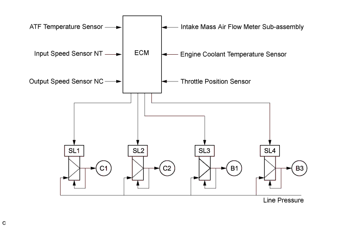
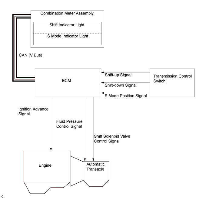
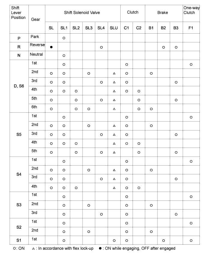
The electronic control system of the U761E automatic transaxle uses the controls listed below.
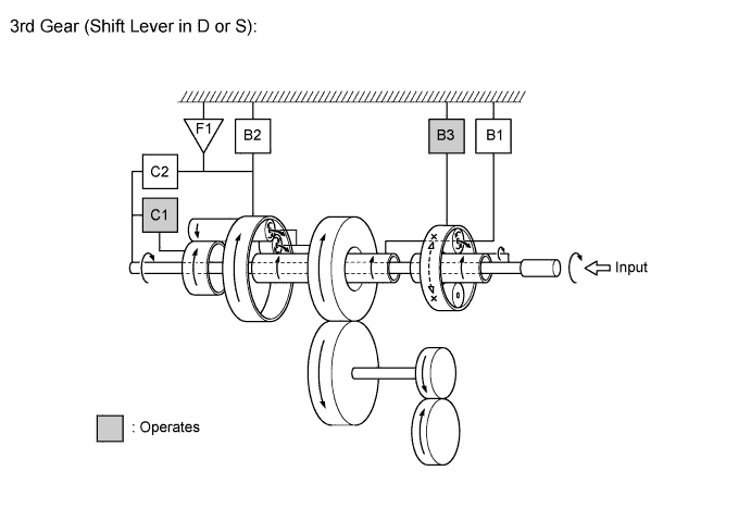
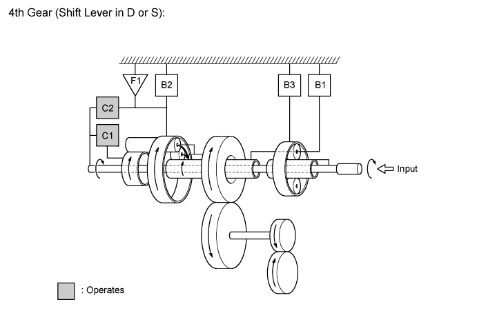
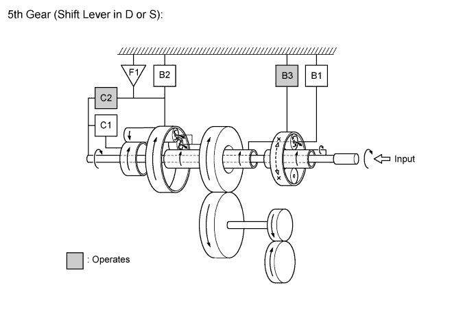
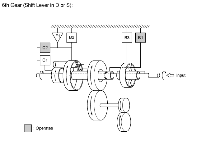
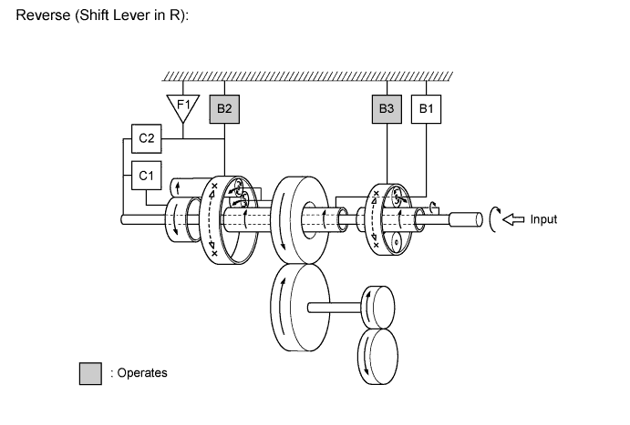
Component Function No. 1 Clutch (C1) Connects the intermediate shaft and the Ravigneaux planetary rear sun gear. No. 2 Clutch (C2) Connects the intermediate shaft and the Ravigneaux planetary ring gear. No. 1 Brake (B1) Prevents the Ravigneaux planetary front sun gear and the underdrive planetary carrier from turning clockwise or counterclockwise. No. 2 Brake (B2) Prevents the Ravigneaux planetary ring gear from turning clockwise or counterclockwise. No. 3 Brake (B3) Prevents the underdrive planetary ring gear from turning clockwise or counterclockwise. No. 1 1-way Clutch (F1) Prevents the Ravigneaux planetary ring gear from turning counterclockwise. Planetary Gears Change the route through which driving force is transmitted in accordance with the operation of each clutch and brake in order to increase or reduce the input and output speed. Shift Solenoid Valve SL1 Controls the No. 1 clutch (C1) pressure. Shift Solenoid Valve SL2 Controls the No. 2 clutch (C2) pressure. Shift Solenoid Valve SL3 Controls the No. 1 brake (B1) pressure. Shift Solenoid Valve SL4 Controls the No. 3 brake (B3) pressure. Shift Solenoid Valve SLU
-
Controls the lock-up clutch pressure.
-
Controls the No. 2 brake (B2) pressure.
Shift Solenoid Valve SLT Controls line pressure. Shift Solenoid Valve SL
-
Switches the lock-up relay valve.
-
Switches the B2 apply control valve and the reverse sequence valve.
Transmission Revolution Sensor Output Speed Sensor NC Detects the speed of the counter gear. Input Speed Sensor NT Detects the input speed of the transaxle. ATF Temperature Sensor Detects the ATF temperature. Engine Coolant Temperature Sensor Detects the engine coolant temperature. Throttle Body with Motor Assembly Throttle Position Sensor Detects the opening angle of the throttle valve. Crank Position Sensor Detects the engine speed. Intake Mass Air Flow Meter Sub-assembly Mass Air Flow Meter Directly detects the intake air mass. Accelerator Pedal Sensor Assembly Detects the accelerator pedal opening angle. Park/Neutral Position Switch Assembly Detects the shift lever position. Lower Shift Lever Assembly Transmission Control Switch
-
Detects that the shift lever is in S.
-
Detects the driver's upshift and downshift operations when the shift lever is in S.
Stop Light Switch Assembly Detects when the brake pedal is depressed. ECM
-
Controls each shift solenoid valve in response to a signal from each sensor and switch.
-
Makes a diagnosis and memorizes the failed section when the ECM detects a malfunction.
Combination Meter Assembly Shift Position and Shift Range Indicator
-
Indicates the shift lever position.
-
Indicates the gear range.
Malfunction Indicator Lamp (MIL) Illuminates to inform the driver when the ECM detects a malfunction. Buzzer Sounds when the downshift operation is rejected. Control Outline Shift Timing Control The ECM sends current to the shift solenoid valves SL1, SL2, SL3, SL4, SL and/or SLU based on signals from various sensors, in order to shift the gears. Clutch to Clutch Pressure Control Controls the pressure that is applied directly to the C1, C2 clutches and B1, B3 brakes by actuating the shift solenoid valves (SL1, SL2, SL3 and SL4) in accordance with signals from the ECM. Line Pressure Control Actuates the shift solenoid valve SLT to control the line pressure in accordance with information from the ECM and the operating conditions of the transaxle. Lock-up Timing Control The ECM sends current to the shift solenoid valves SL and SLU based on signals from various sensors to engage or disengage the lock-up clutch. Flex Lock-up Clutch Control Controls the shift solenoid valve SLU, provides an intermediate mode between the on and off states of the lock-up clutch, and increases the operating range of the lock-up clutch to improve fuel economy. Powertrain Cooperative Control Controls both shift control and engine output control in an integrated way, achieving excellent shift characteristics and drivability. Deceleration Downshift Control To prevent engine speed from decreasing and thereby maintain fuel cut, the ECM performs downshifts before fuel cut ends. Direct Downshift Control Direct downshift control is used. This makes it possible to skip unnecessary shifts, enabling the vehicle to downshift directly from 6th to 3rd or from 5th to 2nd, enhancing downshift response when the accelerator pedal is depressed quickly. Artificial Intelligence Shift Control (AI-shift Control) Based on the signals from various sensors, the ECM determines the road conditions and the intention of the driver. Thus, an appropriate shift pattern is automatically determined, improving drivability. Multi-mode Automatic Transmission The ECM appropriately controls the automatic transaxle in accordance with the range selected while the shift lever is in S. Shift Lock System The shift lock mechanism prevents the shift lever from being moved to any position other than P, unless the ignition switch is ON, and the brake pedal is depressed. Fail-safe If a malfunction is detected in the sensors or solenoids, the ECM performs fail-safe control to prevent the vehicle drivability from being affected significantly. Diagnosis When the ECM detects a malfunction, the ECM records the malfunction and memorizes the information that relates to the fault. -
-
Clutch to Clutch Pressure Control
-
Clutch to clutch pressure control is used for shift control. As a result, shift control in 2nd gear or above is possible without using a one-way clutch, making the automatic transaxle lightweight and compact.
-
Based on the information about transmission input and output speed, engine torque and other items, the ECM controls each clutch and brake accordingly with the optimum fluid pressure and timing, in order to shift the gears. The ECM changes gears using fluid pressure circuits which enable the clutches and brakes (C1, C2, B1 and B3) to be controlled independently, and using high flow SL1, SL2, SL3 and SL4 shift solenoid valves which directly control the line pressure. As a result, highly responsive and excellent shift characteristics have been realized.
-
-
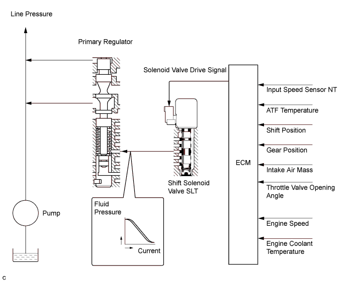
Line Pressure Control
-
The line pressure is controlled using the shift solenoid valve SLT.
-
Through the use of shift solenoid valve SLT, the line pressure is appropriately controlled in accordance with the engine torque information, as well as with the internal operating conditions of the torque converter assembly and the transaxle.
-
Accordingly, the line pressure can be accurately controlled in accordance with the engine output, traveling condition, and the ATF temperature, thus realizing smooth shift characteristics and regulating the workload of the oil pump (reducing unnecessary parasitic losses).
-
-
Lock-up Timing Control
-
The ECM uses lock-up timing control in order to improve the fuel economy in 2nd gear or higher when the shift lever is in D, or when the S6, S5 or S4 range has been selected.
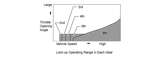
Lock-up Operation: Gear Shift Lever Position or Range D or S6 S5 S4 1st X X X 2nd ▲ ▲ ▲ 3rd ▲ ▲ ▲ 4th ○ ○ ○ 5th ○ ○ - 6th ○ - - Tech Tips
○: Operates
X: Does not operate
-: Not applicable
▲: Only operates while AI-shift control is being performed.
-
-
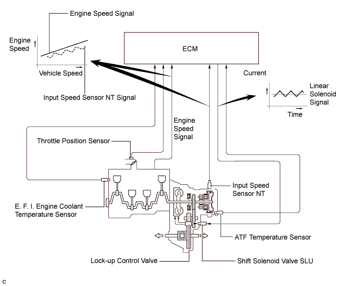
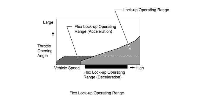
Flex Lock-up Clutch Control
-
During acceleration, the partial control of the power transmission between the lock-up clutch and torque converter assembly greatly boosts the transmission efficiency in accordance with the driving conditions, improving the fuel economy.
-
Even when the vehicle is decelerating (the accelerator pedal is released), flex lock-up clutch control operates. Therefore, the fuel-cut area of the engine has been expanded and fueleconomy has been improved.
-
By allowing flex lock-up clutch control to continue operating during gearshifts, smooth torque transmission has been obtained. As a result, fuel economy and drivability have been improved.
-
For flex lock-up control, H infinity (H∞) control theory is used to achieve a high level of system stability and response to various characteristic changes.
-
The flex lock-up operating range has been expanded. Flex lock-up begins operating once the vehicle starts moving to lower engine speed and improve fuel economy.
Flex Lock-up Operation: Gear Shift Lever Position or Range D S6 S5 S4 1st ○ X X X 2nd ○ ○ ○ ○ 3rd ○ ○ ○ ○ 4th ○* ○* ○* ○* 5th ○* ○* ○* - 6th ○* ○* - - Tech Tips
○: Operates
X: Does not operate
-: Not applicable
*: Flex lock-up clutch control also operates when the vehicle decelerates.
-
-
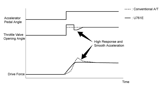
Powertrain Cooperative Control
-
The engine output is appropriately controlled with the Electronic Throttle Control System-intelligent (ETCS-i) in real-time according to the transient force from the torque converter assembly when the vehicle is launched. This achieves a "high response and smooth acceleration", ensuring excellent launch performance.
-
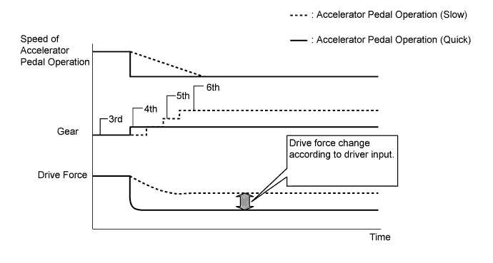
The ECM determines the gear that is to be selected when the accelerator pedal is released (released completely) in accordance with the way the accelerator pedal is released (quickly or slowly) during deceleration. In this way, unnecessary upshifts are prevented during deceleration, matching the driver's intentions. In addition, unintended downshifts are prevented when accelerating the vehicle again, achieving smooth acceleration.
-
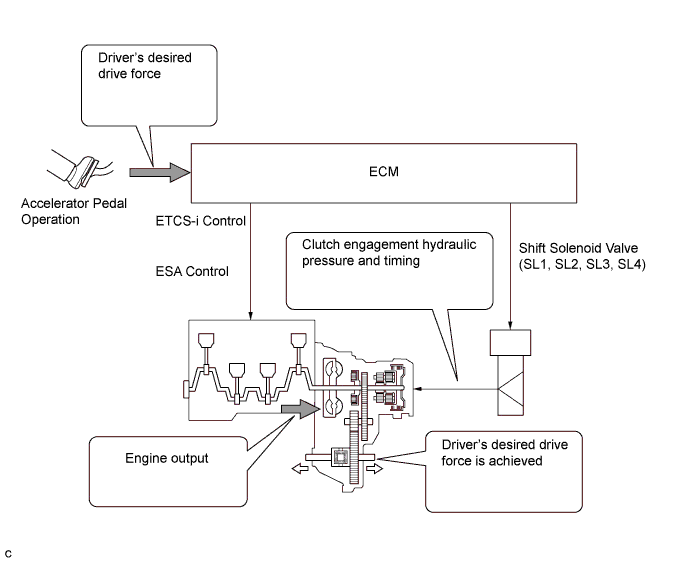
Through cooperative control with the Electronic Throttle Control System-intelligent (ETCS-i) and Electronic Spark Advance (ESA), and electronic control of the engagement and release speed of the clutch and brake hydraulic pressures, quick response and shift shock reduction have been achieved.
-
-
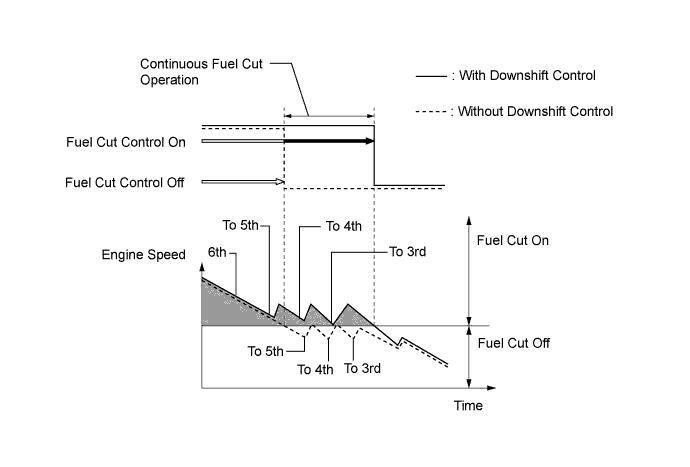
Coast Downshift Control
-
The ECM performs downshift control to help prevent the engine speed from decreasing, thus keeping fuel cut control operating for as long as possible. In this way, fuel economy is improved.
-
For this control, when the vehicle is in 6th gear and starts decelerating, the transaxle downshifts from 6th to 5th, 5th to 4th, and 4th to 3rd before fuel cut control ends so that fuel cut continues operating.
-
-
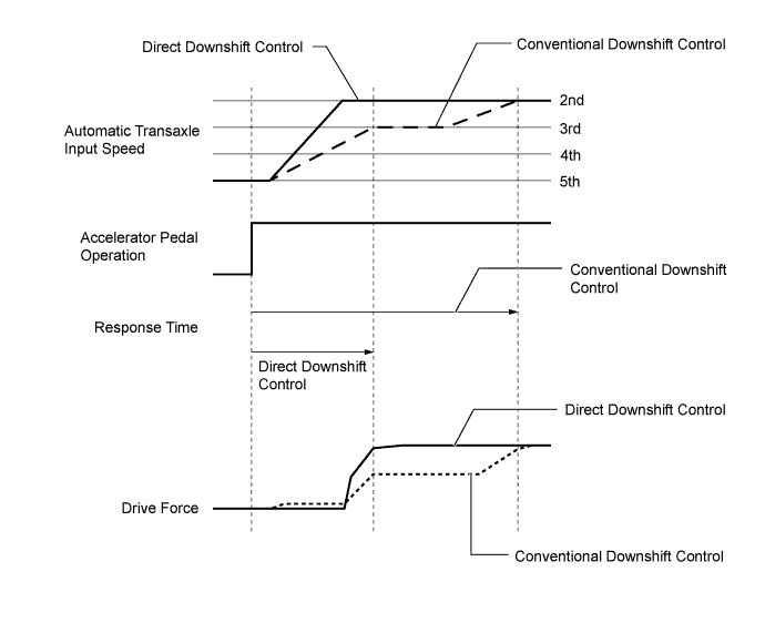
Direct Downshift Control
-
For conventional downshift control, when shifting from 6th to 3rd or 5th to 2nd, downshifts use an intermediate gear in order to achieve smooth acceleration response. In addition to conventional control, direct downshift control is used for this vehicle. This control skips unnecessary shifts, enabling the vehicle to downshift directly from 6th to 3rd or from 5th to 2nd.
-
When the accelerator pedal is depressed quickly, direct downshift control enables direct downshifts with a quick shift response, skipping unnecessary shifts. Direct downshift control places the emphasis on reducing the time required to achieve the target gear. Conventional downshift control is used when the accelerator pedal is depressed slowly, providing smooth acceleration response. As a result, this logic achieves downshift responsiveness in accordance with the driver's intentions.
-
-
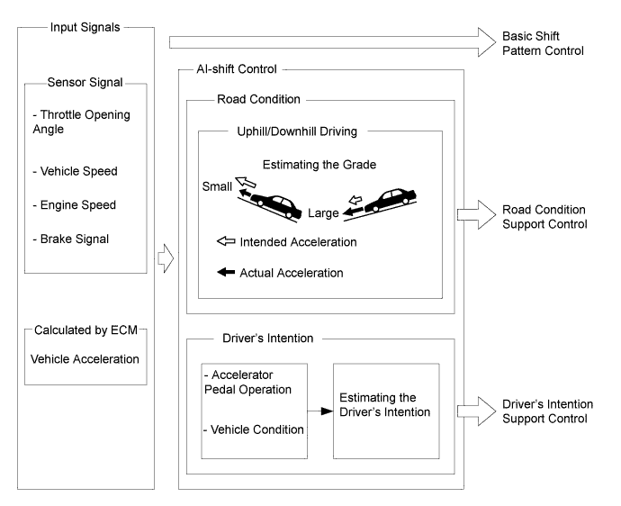
Artificial Intelligence Shift Control (AI-shift Control)
-
The automatic transmission gear is determined by the shift pattern, which uses the vehicle speed and throttle valve opening angle.
-
Additionally, AI-shift control enables the ECM to estimate the road conditions and the driver's intention in order to automatically control the shift pattern in the manner. As a result, a comfortable ride has been achieved.
-
AI-shift control includes road condition support control and driver's intention support control.
-
AI-shift control determines transaxle control based on input signals and automatically changes the shift pattern.
-
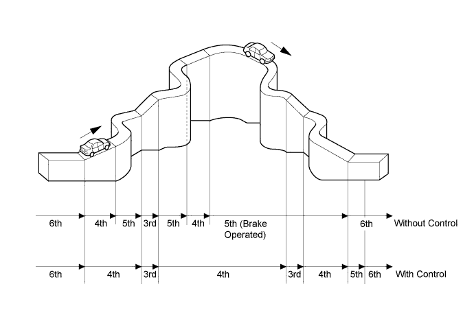
Under road condition support control, the ECM determines the throttle opening angle and the vehicle speed in addition whether the vehicle is being driven uphill or downhill. To achieve the drive force required while driving uphill, this control prevents unnecessary upshifts. To achieve engine braking while driving downhill, this control automatically performs downshifts.
-
The ECM estimates the driver's intention based on the accelerator pedal operation and vehicle operating conditions to select a shift pattern that is well-suited to each driver, without the need to operate the shift pattern select switch used on conventional models.
-
-
Multi-mode Automatic Transmission
-
Multi-mode Automatic Transmission is designed to allow the driver to switch between gear ranges. By moving the shift lever to S and then moving the shift lever toward "+" or "-", the driver can select the desired shift range. Thus, the driver is able to shift gears with a manuallike feel.
-
This Multi-mode Automatic Transmission is designed to allow the driver to switch gear ranges; it is not for manually selecting single gears.
-
When the vehicle is being driven at a speed that is higher than the maximum safe speed for a downshift, any attempt to shift to a lower range by operating the shift lever will not be performed. This is done in order to protect the automatic transaxle. In this case, the ECM sounds the buzzer in the combination meter assembly twice to alert the driver.
-
The driver can select S mode by moving the shift lever to S. At this time, the 4th or 5th shift range will be selected according to the vehicle speed (during AI-shift control, however, the 3rd shift range may be selected).
-
Under this control, the ECM performs shift control within the usable gear range that the driver selects. As with an ordinary automatic transaxle, it shifts to 1st gear when the vehicle is stopped.
-
The shift lever position and the shift range are indicated by the shift indicator light in the combination meter assembly (the shift range is shown only when the shift lever is in S, and it is not shown when the shift lever is in P, R, N or D).
-
When the shift lever is in S, the S mode indicator light in the combination meter assembly illuminates. The shift indicator light indicate the shift range that the driver has selected.
-
Holding the shift lever toward "+" with the shift lever in S will change the shift range to the S6 range regardless of the current range (S1 to S5).
-
In order to prevent excessive engine speed, a function is used that automatically selects a higher shift range before engine speed becomes excessive.
-
In order to protect the automatic transmission, a function is adopted that automatically selects a higher shift range when the fluid temperature is high.
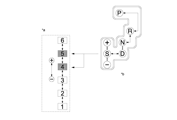
Text in Illustration *a Transition of Shift Ranges *b Shift Pattern 
Default Shift Range - - Usable Gear Chart Shift Range Shift Indicator Light Usable Gear S6 6 1st to 6th S5 5 1st to 5th S4 4 1st to 4th S3 3 1st to 3rd S2 2 1st to 2nd S1 1 1st
-
-
Shift Lock System
-
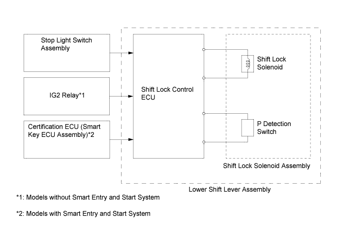
The shift lock system is controlled by the shift lock control ECU.
-
The shift lock mechanism prevents the shift lever from being moved to any position other than P, unless the ignition switch is ON, and the brake pedal is depressed. This mechanism helps to prevent unintentional acceleration.
-
The shift lock system mainly consists of the shift lock control ECU, shift lock solenoid assembly and shift lock release button.
-
The shift lock control ECU uses the P detection switch to detect the shift lever position, and receives inputs from the stop light switch assembly and the certification ECU (smart key ECU assembly) or IG2 relay. Upon receiving these signals, the shift lock control ECU turns on the shift lock solenoid in order to release the shift lock.
-
-
-
CONSTRUCTION
-
Differential Case
-
A differential pre-load mechanism, in which the conical spring is located between the side gear and the side gear washer, is used.
-
The load of the conical spring applies a friction force to the sliding area, improving straightline stability and steering stability.
-
Under light load and low differential rotation speeds, due to the friction force of the sliding area, the differential limit torque for the left and right wheels is achieved within the range of the conical spring allowable load. At middle and high load ranges, which are beyond the allowable load of the conical spring, the system performs as an open differential.
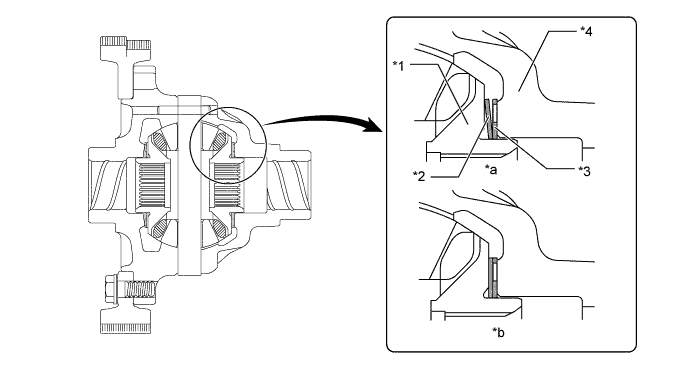
Text in Illustration *1 Side Gear *2 Conical Spring *3 Side Gear Washer *4 Differential Case *5 Light Load Range *6 Middle and High Load Range 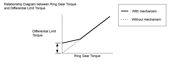
-
-
Torque Converter assembly
-
A compact, lightweight and high-capacity torque converter assembly is used.
-
This torque converter assembly has appropriately designed fluid passages and impeller configuration, resulting in substantially enhanced transmission efficiency to ensure good starting, acceleration and fuel economy.
-
Furthermore, a hydraulically operated lock-up mechanism which cuts power transmission losses due to slippage at medium and high speeds is used.
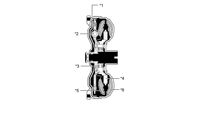
Text in Illustration *1 Lock-up Clutch *2 Lock-up Damper *3 One-way Clutch *4 Stator *5 Turbine Runner *6 Pump Impeller
-
-
Oil Pump Assembly
-
The oil pump is operated by the torque converter assembly. It lubricates the planetary gear units and supplies operating fluid pressure for hydraulic control.
-
The pump cover is made of aluminum to reduce weight.
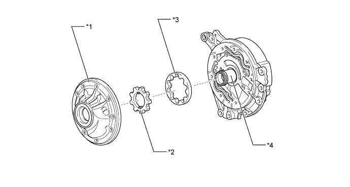
Text in Illustration *1 Front Oil Pump and Gear Body Sub-assembly *2 Front Oil Pump Drive Gear *3 Front Oil Pump Driven Gear *4 Stator Shaft Assembly
-
-
Oil Strainer
-
A felt type valve body oil strainer assembly is used because it is lightweight, offers excellent contamination capturing ability, and is more reliable. This valve body oil strainer assembly is maintenance-free.
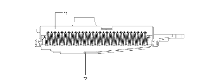
Text in Illustration *1 Filter *2 Strainer
-
-
ATF Filling Procedure
-
A special ATF filling procedure is used in order to improve the accuracy of the ATF level when the transaxle is being repaired or replaced. As a result, the oil filler tube and the oil level gauge used in a conventional automatic transmission have been discontinued, eliminating the need to inspect the fluid level as a part of routine maintenance.
-
This filling procedure uses the refill plug, overflow plug, ATF temperature sensor, and the D indicator. For details about the ATF filling procedure, refer to the Repair Manual.
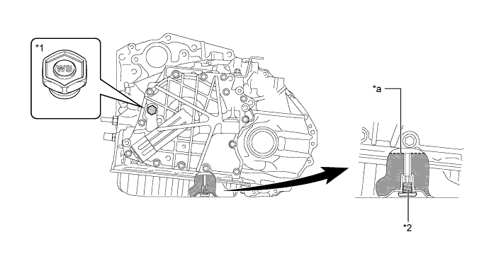
Text in Illustration *1 Refill Plug *2 Overflow Plug *a Proper Level - -
-
-
Planetary Gear Unit
-
The 6-speed configuration has been achieved by using 2 planetary gear units, creating a 6- speed automatic transaxle.
-
A Ravigneaux type planetary gear unit is used as the rear gear unit. The gear unit consists of pairs of sun gears (front and rear) and planetary pinion gears (long and short) with different diameters within a single planetary gear.
-
A centrifugal fluid pressure canceling mechanism is used in the C1 and C2 clutches that are applied when shifting between 1st to 6th gears.
-
The shapes of the grooves in the clutches and brake linings have been optimized in order to reduce drag.
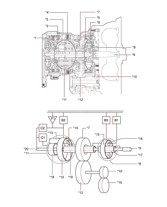
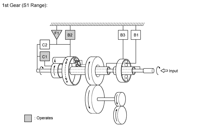
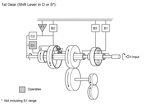
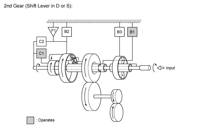
Text in Illustration *1 No. 1 Clutch (C1) *2 No. 2 Clutch (C2) *3 No. 1 One-way Clutch (F1) *4 No. 2 Brake (B2) *5 No. 3 Brake (B3) *6 No. 1 Brake (B1) *7 Counter Drive Gear *8 Underdrive Planetary Gear Unit *9 Input Shaft *10 Differential Drive Pinion *11 Ravigneaux Planetary Gear Unit *12 Counter Driven Gear *13 Long Pinion Gear *14 Short Pinion Gear *15 Ring Gear *16 Pinion Gear *17 Sun Gear *18 Rear Sun Gear *19 Front Sun Gear *20 Intermediate Shaft -
The functions of the clutches and brakes are as follows:
Component Function C1 No. 1 Clutch Connects the intermediate shaft and Ravigneaux planetary rear sun gear. C2 No. 2 Clutch Connects the intermediate shaft and Ravigneaux planetary ring gear. B1 No. 1 Brake Prevents the Ravigneaux planetary front sun gear and underdrive planetary carrier from turning either clockwise or counterclockwise. B2 No. 2 Brake Prevents the Ravigneaux planetary ring gear from turning either clockwise or counterclockwise. B3 No. 3 Brake Prevents the underdrive planetary ring gear from turning either clockwise or counterclockwise. F1 No. 1 One-way Clutch Prevents the Ravigneaux planetary ring gear from turning counterclockwise. Planetary Gears These gears change the route through which driving force is transmitted, in accordance with the operation of each clutch and brake, in order to increase or reduce the input and output speeds.
-
-
Centrifugal Fluid Pressure Canceling Mechanism
-
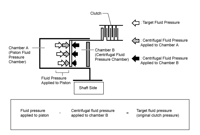
For the following reason, a centrifugal fluid pressure canceling mechanism is used on the C1 and C2 clutches.
-
Clutch shifting operations are affected not only by the valve body controlled fluid pressure but also by centrifugal fluid pressure from the fluid that is present in the clutch piston oil pressure chamber (chamber A). The centrifugal fluid pressure canceling mechanism uses chamber B to reduce the effects of the centrifugal fluid pressure due to the fluid in chamber A. As a result, smooth shifting with excellent response is achieved.
Text in Illustration *1 C1 *2 C2 *3 Chamber A *4 Chamber B *5 Piston - - -
Chamber B is filled by fluid supplied to the shaft for lubrication. As a result of filling chamber B, there is the same amount of fluid pressure due to centrifugal force on both sides of the piston. This cancels the effect of fluid pressure on the piston due to centrifugal force. Accordingly, it is not necessary to discharge the fluid through the use of a check ball, and highly responsive and smooth shifting characteristics are achieved.
-
-
Counter Drive Gear
-
Angular ball bearings are used to support the counter drive gear and the Ravigneaux planetary gear unit, reducing the rolling resistance and noise.
Text in Illustration *1 Angular Ball Bearing *2 Counter Drive Gear
-
-
Clutch and Brake Pistons
-
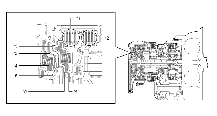
2 types of pistons are used; a non-split piston that acts in the push direction for the No. 1 clutch (C1) operation, and a split piston that acts in the pull direction for the No. 2 clutch (C2) operation. These 2 types of pistons contribute to making the entire clutch structure compact.
-
A split type piston is adopted for the C2 piston, achieving a compact design.
-
A wave spring is used to ensure C2 piston transfer efficiency.
-
By setting the piston for the No. 3 brake (B3) operation around the counter drive gear, the brake structure has been made more compact.
-
The opening of the B3 piston oil drain holes has been enlarged to reduce oil agitation, contributing to improvements in fuel economy performance.
Text in Illustration *1 Piston (Split Type) *2 Wave Spring *3 Piston (Non-split Type) *4 Divided Portion *5 Piston *6 Counter Drive Gear *7 No. 1 Clutch (C1) *8 No. 2 Clutch (C2) *9 No. 3 Brake (B3) - - -
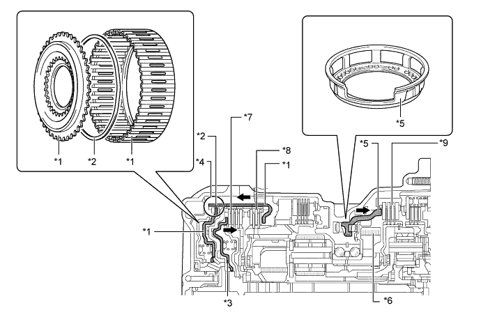
The clutch and brake portions use low-loss grooved shapes, and a friction material with waves is also used for the brake portion. As a result, losses due to drag are drastically reduced and high efficiency is achieved.
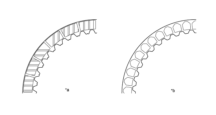
Text in Illustration *a Clutch Portion *b Brake Portion -
The cage opening area of the one-way clutch has been increased to optimize the flow of surrounding lubrication and reduce oil agitation, contributing to improvements in fuel economy performance.
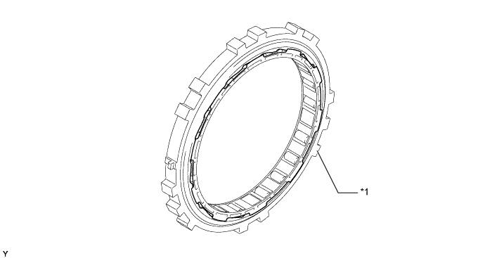
Text in Illustration *1 No. 1 One-way Clutch (F1) - -
-
-
Transmission Valve Body Assembly
-
The transmission valve body assembly consists of the No. 1 upper, No. 2 upper and lower valve bodies and 7 shift solenoid valves (SL1, SL2, SL3, SL4, SLU, SLT, SL).
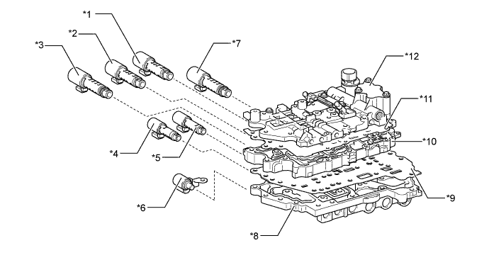
Text in Illustration *1 Shift Solenoid Valve SL3 *2 Shift Solenoid Valve SL1 *3 Shift Solenoid Valve SL2 *4 Shift Solenoid Valve SLT *5 Shift Solenoid Valve SLU *6 Shift Solenoid Valve SL *7 Shift Solenoid Valve SL4 *8 Lower Valve Body *9 Valve Body Plate *10 Upper Valve Body *11 No. 2 Valve Body Plate *12 No. 2 Upper Valve Body 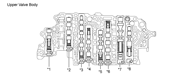
Text in Illustration *1 Solenoid Modulator Valve *2 B2 Control Valve *3 B2 Apply Control Valve *4 Clutch Apply Control Valve *5 Clutch Control Valve *6 Sequence Valve *7 Primary Regulator Valve *8 B1 Apply Control Valve 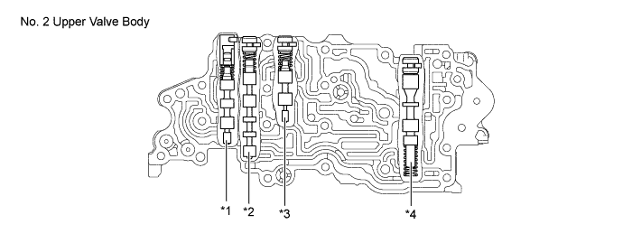
Text in Illustration *1 Lock-up Control Valve *2 Lock-up Relay Valve *3 Reverse Sequence Valve *4 Secondary Regulator Valve 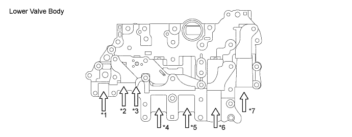
Text in Illustration *1 Shift Solenoid Valve SL Installation Position *2 Shift Solenoid Valve SLT Installation Position *3 Shift Solenoid Valve SLU Installation Position *4 Shift Solenoid Valve SL2 Installation Position *5 Shift Solenoid Valve SL1 Installation Position *6 Shift Solenoid Valve SL3 Installation Position *7 Shift Solenoid Valve SL4 Installation Position - -
-
-
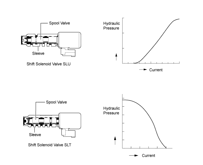
Shift Solenoid Valves SL1, SL2, SL3, SL4, SLU and SLT
-
In order to provide a hydraulic pressure that is proportional to the current that flows to the solenoid coil, shift solenoid valves SL1, SL2, SL3, SL4, SLU and SLT linearly control the line pressure and clutch and brake engagement pressure based on the signals from the ECM.
-
Shift solenoid valves SL1, SL2, SL3 and SL4 are high flow linear solenoid valves that can supply more pressure than conventional ones. These shift solenoid valves control engagement elements by directly regulating the line pressure without using a pressure regulation valve (control valve) or a pressure reduction valve (solenoid modulator valve). Thus, the number of valves and the length of the valve body fluid passage have been reduced, the shifting response has been increased and shift shock has been minimized.
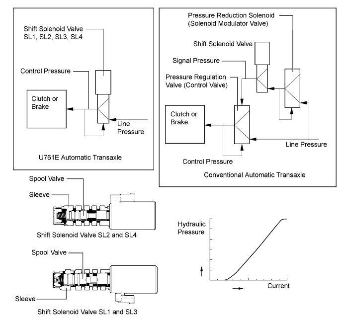
Shift Solenoid Valve Function SL1 C1 clutch pressure control SL2 C2 clutch pressure control SL3 B1 brake pressure control SL4 B3 brake pressure control SLU - Lock-up clutch pressure control
- B2 brake pressure control
SLT Line pressure control
-
-
Shift Solenoid Valve SL
-
Shift solenoid valve SL is a 3-way solenoid valve.
-
A filter is provided at the tip of the solenoid valve to further improve operational reliability.
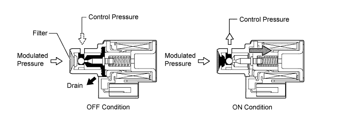
Shift Solenoid Valve Type Function SL 3-way
-
- Switches the lock-up relay valve.
-
- Switches the B2 apply control valve and the reverse sequence valve.
-
-
-
ECM
-
The ECM performs transaxle control.
-
A label, on which the automatic transaxle compensation values and Quick Response (QR) code are printed, is attached on the top of the automatic transaxle. The label contains encoded information about the characteristics of the automatic transaxle. When the automatic transaxle is replaced, allow the ECM to learn the characteristics of the automatic transaxle by inputting the automatic transaxle compensation values into the ECM using the Global TechStream (GTS). In this way, the shift control performance immediately after replacement of the automatic transaxle is improved. For details, refer to the Repair Manual.
-
The QR code, which requires a special tool to read, is used at the vehicle assembly plant.
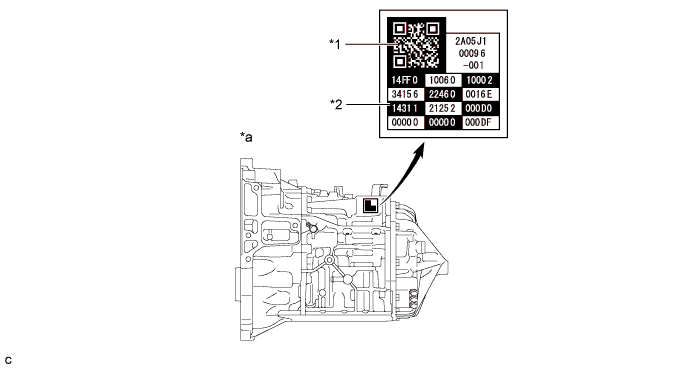
Text in Illustration *1 QR Code *2 Automatic Transaxle Compensation Value *a Automatic Transaxle Front View - - Tech Tips
What are Quick Response (QR) Codes?
-
QR code, a matrix symbology consisting of an array of nominally square cells, allows omni-directional, high-speed reading of large amounts of data.
-
QR codes encode many types of data such as numeric, alphanumeric, kanji, kana and binary codes. A maximum of 7,089 characters (numeric) can be encoded.
-
QR codes (2D code) contain information in the vertical and horizontal directions, whereas bar codes only contain data in one direction. QR codes (2D code) hold considerably greater volumes of information than bar codes.
-
-
-
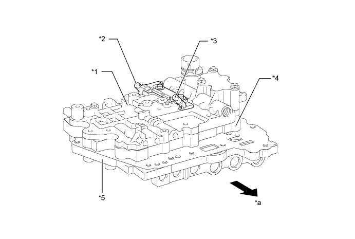
ATF Temperature Sensor
-
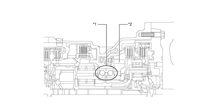
The ATF temperature sensor is installed in the transmission valve body assembly for direct detection of the fluid temperature.
-
The ATF temperature sensor is used for hydraulic pressure control. This sensor is used for fine-tuning the pressure that is used to apply clutches and brakes in the transmission. This helps to ensure smooth shift quality.
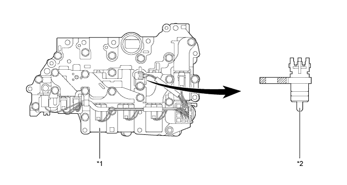
Text in Illustration *1 Lower Valve Body *2 ATF Temperature Sensor
-
-
Transmission Revolution Sensor
-
The U761E automatic transaxle uses an input speed sensor NT and a output speed sensor NC. Thus, the ECM can detect the timing of the shifting of the gears and appropriately control the engine torque and hydraulic pressure in response to the various conditions.
-
The input speed sensor NT detects the input speed of the transaxle. The No. 2 clutch piston is used as the timing rotor for this sensor.
-
The output speed sensor NC detects the speed of the counter gear. The counter drive gear is used as the timing rotor for this sensor.
-
A Hall type speed sensor consists of a magnet and a Hall IC. The Hall IC converts the changes in magnetic flux density that occur through the rotation of the timing rotor into an electric signal, and outputs the signal to the ECM.
Text in Illustration *1 No. 2 Upper Valve Body *2 Transmission Revolution Sensor
- Input Turbine Speed Sensor
*3 Transmission Revolution Sensor
- Output Speed Sensor NC
*4 No. 1 Upper Valve Body *5 Lower Valve Body - - *a Engine Side - -
-
-
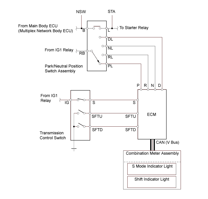
Transmission Control Switch and Park/Neutral Position Switch Assembly
-
The ECM uses these switches to detect the shift lever position.
-
The park/neutral position switch assembly sends the P, R, N and D position signals to the ECM. The ECM transmits signals to the combination meter assembly for the shift position indicator lights (P, R, N and D) in response to the signals received from the switch.
-
The transmission control switch is installed inside the lower shift lever assembly to inform the ECM of the shift lever position.
-
Switch terminal S is used to detect whether the shift lever is in D or S, and terminals SFTU and SFTD are used to detect the operation of the shift lever if it is moved to "+" (forwards) or "-" (backwards) when S mode is selected. By transmitting signals to the ECM, the transmission control switch turns on both the shift indicator light and the S mode indicator light when the shift lever is moved to S, and indicates the selected range through the shift indicator light.
-
-
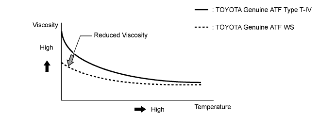
Automatic Transmission Fluid (ATF) WS
-
TOYOTA genuine ATF WS is used to reduce the resistance of the ATF and improve the fuel economy by reducing its viscosity in the practical operating temperature range. At higher-fluid temperatures, the viscosity is the same as that of TOYOTA genuine ATF Type T-IV, to ensure the durability of the automatic transmission.
-
There is no interchangeability between the TOYOTA genuine ATF WS and other types of ATF (D-II, DIII or TOYOTA genuine ATF Type T-IV).
-
-
-
OPERATION
-
Transmission Power Flow
-
-
FAIL-SAFE
The fail-safe function minimizes the loss of operability when an abnormality occurs in a sensor or shift solenoid valve. For details, refer to the Repair Manual.
-
DIAGNOSIS
-
When the ECM detects a malfunction, the ECM records the malfunction and memorizes the information related to the fault. Furthermore, the ECM illuminates or blinks the Malfunction Indicator Lamp (MIL) in the combination meter assembly to inform the driver.
-
The ECM will also store Diagnostic Trouble Codes (DTCs) of the malfunctions. The DTCs stored in the ECM are output to an Global TechStream (GTS) via the ECM and the DLC3. For details, refer to the Repair Manual.
Tech Tips
To clear a DTC that is stored in the ECM, use an Global TechStream (GTS), disconnect the cable from the battery terminal for 1 minute or longer.
-