INTAKE SYSTEM DETAILS
-
CONSTRUCTION
-
Air Cleaner
-
A paper type air cleaner filter element sub-assembly is used.
-
A mass air flow meter sub-assembly is provided for the air cleaner cap sub-assembly.
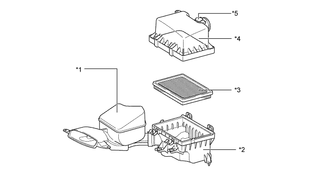
Text in Illustration *1 Air Cleaner Inlet Assembly *2 Air Cleaner Case Sub-assembly *3 Air Cleaner Filter Element Sub-assembly *4 Air Cleaner Cap Sub-assembly *5 Mass Air Flow Meter Sub-assembly - -
-
-
Intake Manifold
-
A resin intake manifold is used. This manifold has 5 small pieces integrated using vibration welding, achieving a lightweight design.
-
EGR delivery is integrated into the intake manifold and designed in a tournament arrangement. This allows EGR gas to be equally distributed to the cylinders while also achieving a reduced number of components and a lightweight design. In addition, the ribs are cleverly positioned to achieve both a reduction in exhaust sounds and a lightweight design.
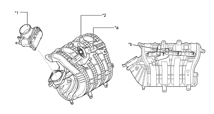
Text in Illustration *1 Throttle Body with Motor Assembly *2 Intake Manifold *a EGR Delivery *b EGR Gas Flow
-
-
Throttle Body with Motor Assembly
-
A linkless type throttle body with motor assembly in which the throttle position sensor and the throttle are integrated is used. It realizes excellent throttle valve control.
-
The throttle control motor uses a DC motor with excellent response and minimal power consumption. The ECM performs duty ratio control of the direction and the amperage of the current that flows to the throttle control motor in order to regulate the throttle valve angle.
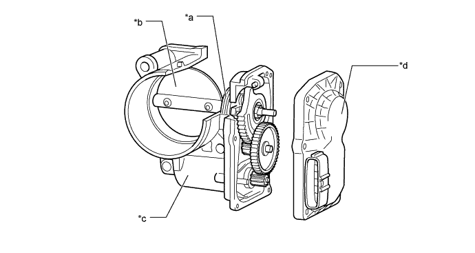
Text in Illustration *a Return Spring *b Throttle Valve *c Throttle Control Motor *d Throttle Position Sensor
-
-