ТОПЛИВНАЯ СИСТЕМА
-
SYSTEM CONTROL
-
Diesel EFI System
-
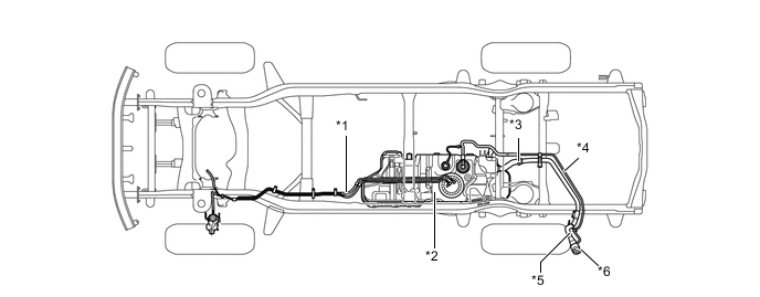
In this system, the ECM sends signals to the injection pump in order to control the injection timing, injection volume and idling speed.
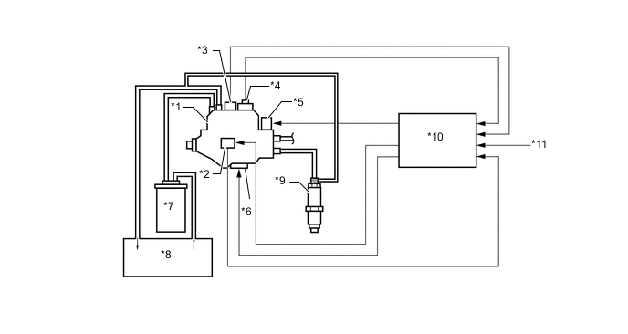
Text in Illustration *1 Injection Pump Assembly *2 Injection Pump Correction Unit *3 Fuel Temperature Sensor *4 Engine Speed Sensor *5 Spill Control Valve *6 Timing Control Valve *7 Fuel Filter Assembly *8 Fuel Tank *9 Injection Nozzle *10 ECM *11 Various Sensors - -
-
-
Dual Fuel Tank
-
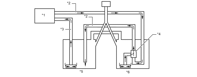
On the models with dual fuel tank, the return tube passes through the sub fuel tank and returns to the main fuel tank. This construction utilizes the heat of the return fuel that has been warmed by the engine to prevent the temperature in the sub fuel tank from decreasing.
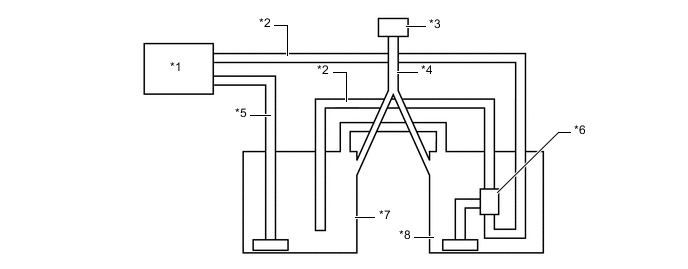
Text in Illustration *1 Engine *2 Return Tube *3 Fuel Inlet *4 Fuel Filler Pipe *5 Main Tube *6 Jet Pump *7 Main Fuel Tank *8 Sub Fuel Tank
-
-
-
CONSTRUCTION
-
Injection Pump Assembly
-
A VE distribution type electronically controlled injection pump is used.
-
A spill control valve, timing control valve, fuel temperature sensor, engine speed sensor, and injection pump correction unit is used on the injection pump.
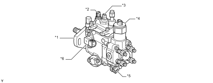
Text in Illustration *1 Injection Pump Assembly *2 Fuel Temperature Sensor *3 Engine Speed Sensor *4 Spill Control Valve *5 Timing Control Valve *6 Injection Pump Correction Unit
-
-
Fuel Filter Assembly
-
The cartridge type fuel filter is used.
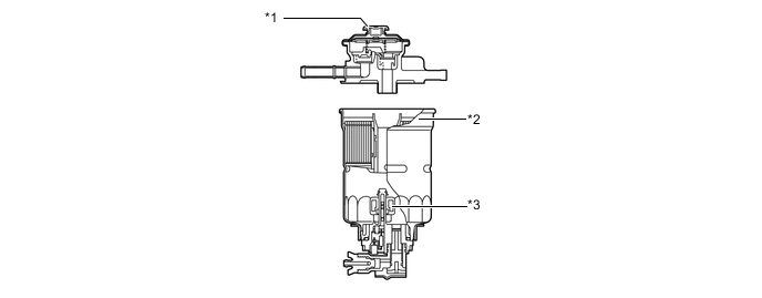
Text in Illustration *1 Priming Pump *2 Filter Cartridge *3 Fuel Sedimenter Level Warning Switch - - -
A paper filter element that offers high filtering efficiency and captures even the smallest particles is used.
-
-
Fuel Tank
-
On the models with a spare tire installed on the under floor, a single fuel tank is used.
-
On the models with a spare tire installed on the back door, a dual fuel tank is used.
-
A multiplex layer plastic fuel tank is used on the models with single fuel tank model, and as the main fuel tank on the models with dual fuel tank.
Text in Illustration (Models with Single Fuel Tank:) *1 Main Tube *2 Fuel Tank (Made of Multiplex Layer Plastic) *3 Fuel Filler Hose *4 Circulate Tube *5 Fuel Filler Pipe *6 Fuel Tank Cap 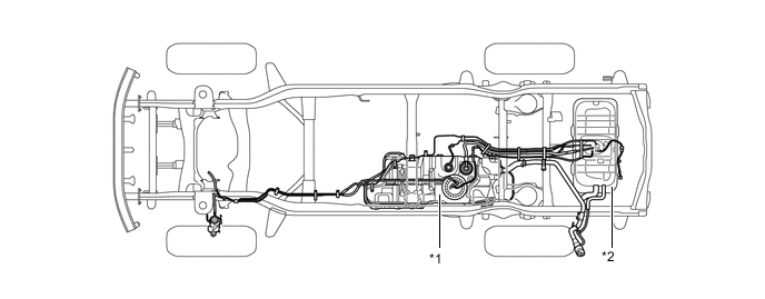
Text in Illustration (Models with Dual Fuel Tank:) *1 Main Fuel Tank (Made of Multiplex Layer Plastic) *2 Sub Fuel Tank (Made of Steel) -
The multiplex layered plastic fuel tank consists of 6 layers of 4 types of materials.
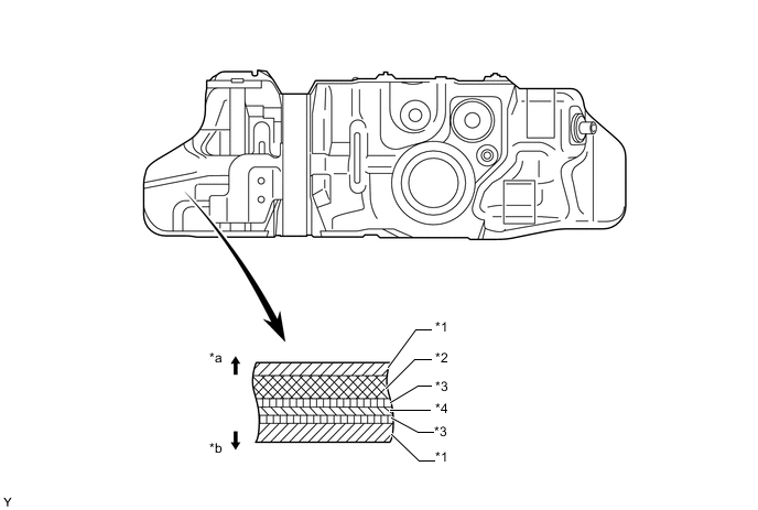
Text in Illustration *1 High Density Polyethylene (HDPE) *2 Regrind Material *3 Adhesive *4 Ethylene Vinyl Alcohol Copolymer (EVOH) *a Fuel Tank Outside *b Fuel Tank Inside -
On the models with dual fuel tank, a jet pump is provided in the sub fuel tank. The return fuel from the engine passes through the orifice in the jet pump and returns to the main fuel tank. Because the flow speed of the return fuel increases as it passes through the orifice, a vacuum is created near the exit of the orifice. This vacuum causes the fuel to be drawn from the sub fuel tank, and a prescribed volume of fuel flows to the main fuel tank together with the return fuel.
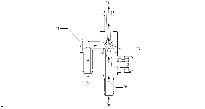
Text in Illustration *1 Jet Pump Assembly *2 Orifice *a To Main Fuel Tank *b From Sub Fuel Tank *c Return Fuel *d Fuel Flow
-
-
-
OPERATION
-
Fuel Filter Assembly
-
When the water in the sedimenter section reaches a certain amount, the fuel sedimenter level warning switch comes on, the warning light in the combination meter illuminates, and the multi buzzer sounds.
-
-
Dual Fuel Tank
-
The fuel to the engine is always supplied from the main fuel tank. The return fuel passes through the sub fuel tank and returns to the main fuel tank. During this process, the return fuel from the engine actuates the jet pump located in the sub fuel tank. A prescribed volume of fuel is then drawn from the sub fuel tank, and flows to the main fuel tank together with the return fuel.
-
In this system, the fuel amount fed from the injection pump is more than the fuel amount consumed by the engine, therefore, the fuel in the sub fuel tank side runs out quicker than the other.
Text in Illustration *1 Engine *2 Return Tube *3 Main Tube *4 Jet Pump *5 Main Fuel Tank *6 Sub Fuel Tank
-
-