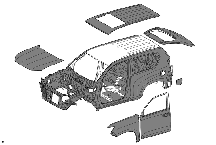
BODY STRUCTURE
-
FUNCTION
-
Impact Absorbing Structure for Frontal Collision
-
A structure that ensures collision energy absorption efficiency, dissipates impact, and minimizes cabin deformation during a frontal collision has been achieved.
-
The front body pillar inner and the roof side rail reinforcement inner are overlapped. The buckling force and the duration of buckling during a frontal collision have both been increased, thus suppressing the body deformation of the front door periphery.
-
The front body pillar reinforce lower is divided into two, and is structurally overlapped to suppress the deformation of the front door periphery by the load input from the tires during a frontal collision.
-
Rocker panel outer reinforcement made from ultra high-tensile strength steel has been added to suppress the deformation of the front door periphery by the load input from the tires during a frontal collision.
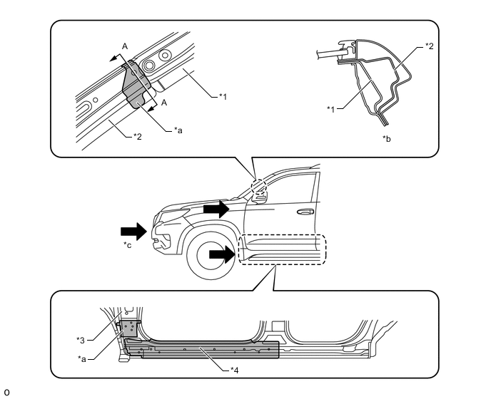
*1 Roof Side Rail Reinforcement Inner *2 Front Body Pillar Inner *3 Front Body Pillar Reinforcement Lower *4 Rocker Panel Outer Reinforcement *a Overlap Area *b A - A Cross Section *c Impact Energy - -
-
-
-
Impact Absorbing Structure for Side Collision
-
A structure that ensures collision energy absorption efficiency, dissipates impact, and minimizes cabin deformation during a side collision has been achieved.
-
High-tensile strength steel is used for the front body pillar, center body pillar, and roof side rail. In addition, ultra high-tensile strength steel is used for the center body pillar and rocker, thus ensuring high strength in a side collision.
-
Cross members are optimally positioned in the floor. Cross members efficiently deform to suppress the level of body intrusion during a side collision.
-
Closed cross section roof headlining reinforcement is provided to support the front body pillar, center body pillar, and roof side rail.
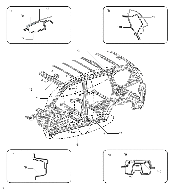
*1 Front Body Pillar *2 Roof Headlining Reinforcement *3 Roof Side Rail Reinforcement *4 Center Body Pillar Reinforcement *5 Cross Member *6 Rocker Panel Reinforcement *7 Roof Headlining Lower *8 Roof Headlining Upper *9 Ultra High-tensile Strength Steel *10 High-tensile Strength Steel *a A - A Cross Section *b B - B Cross Section *c C - C Cross Section *d D - D Cross Section *e Closed Section - - -
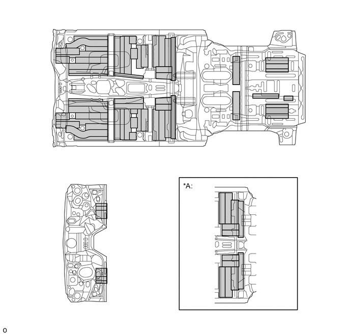
Front floor to brace reinforcement is provided as a load transmission material, in order to efficiently transmit load input from the center pillar to the front floor cross member No.1 and floor cross member. In addition, a load transmission bracket is provided between the rocker inner reinforcement and chassis frame and input load from the rocker panel outer is transmitted to the frame, thus reducing the level of the body deformation.
-
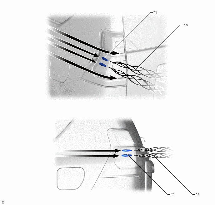
An energy absorbing pad is provided inside the door panel and door trim to enhance the transmission efficiency of collision load and the reduction of the injury criterion on the passenger's lumbar.
-
A crushable structure is provided for the armrest, thus enhancing the reduction of the injury criterion on the passenger's lumbar.
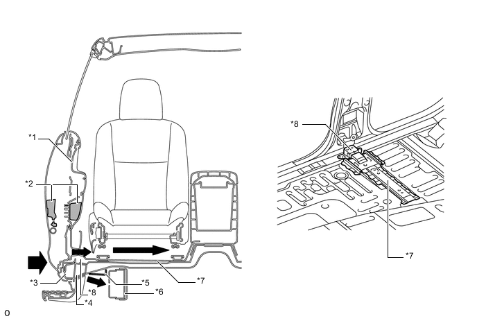
*1 Door Trim *2 Energy Absorbing Pad *3 Rocker Panel Outer *4 Rocker Panel Inner *5 Load Transmission Bracket *6 Frame *7 Front Floor Cross Member No. 1 *8 Front Floor to Brace Reinforcement 
Impact Energy - -
-
-
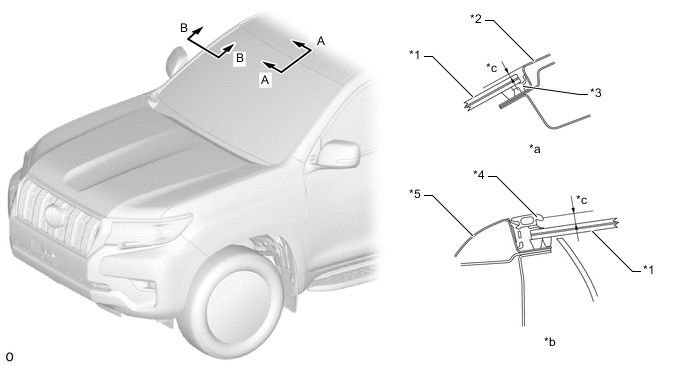
A head impact protection structure is used. With this type of construction, if the occupant's head hits against the roof side rail and pillar in reaction to a collision, the inner panel of the roof side rail and pillar collapses to help reduce the impact.
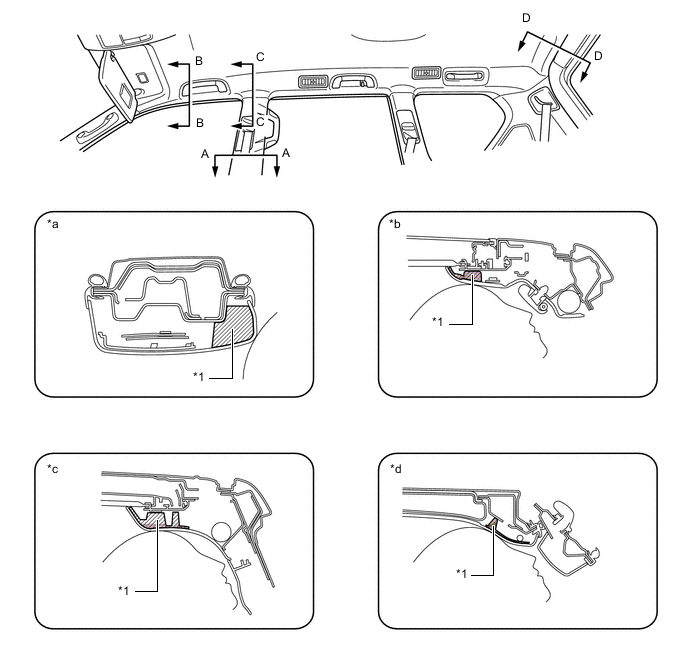
*1 Energy Absorber - - *a A - A Cross Section *b B - B Cross Section *c C - C Cross Section *d D - D Cross Section
-
-
Lessening Pedestrian Head Injury
-
A vertical frame structure is provided in the hood to enable the hood as a whole to dampen the impact.
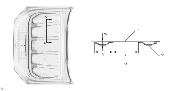
*1 Hood Panel *2 Hood Inner Panel *a A - A Cross Section *b Optimized Bead Height *c Optimized Frame Width *d Optimized Frame Pitch -
An auxiliary catch integrated with a hood lock is used. The auxiliary catch is shaped to enable impact absorption. During a collision with a pedestrian, the auxiliary catch efficiently deforms to absorb the impact, with the aim of reducing the predicted impact to the pedestrian's head.
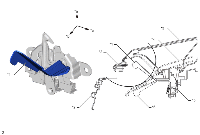
*1 Auxiliary Catch *2 Radiator Grille *3 Hood Panel *4 Hood Panel (after Impact Absorption) *5 Hood Lock *6 Auxiliary Catch (after Impact Absorption) *a Upside *b Front side *c Outside - - -
A collision stopper has been located to allow the hood hinge arm to rotate further downwards than the fully closed position without any interference. This enables the hood hinge arm to rotate downwards when a pedestrian collides with the hood panel, thus reducing collision energy and ensuring pedestrian protection performance.
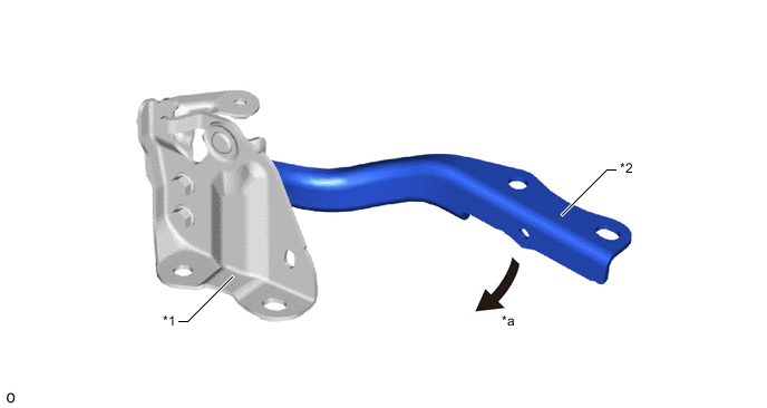
*1 Hood Hinge Bracket *2 Hood Hinge Arm *a Rotate Downward - - -
Load reduction holes and fold lines are provided on the front and rear walls of the hood lock hook reinforcement to optimize strength. During a collision with a pedestrian, a space for the pedestrian's head to stroke is ensured, with the aim of reducing the predicted impact to the pedestrian's head.
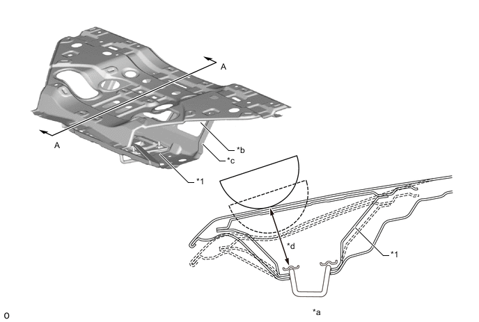
*1 Hood Lock Hook Reinforcement - - *a A - A Cross Section *b Load Reduction Holes *c Fold Line *d Ensured Stroke -
The cowl panel has an open structure. In the event of a collision with a pedestrian, this structure helps lessen the impact inflicted by the cowl to the head of the pedestrian.
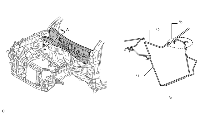
*1 Cowl Panel *2 Cowl Top Ventilator Louver *a A - A Cross Section *b Open Structure -
Fender brackets (fender apron reinforcement plate, front fender apron reinforcement rear and front fender apron reinforcement) are used in the joint portion of the front fender. The height of the fender bracket and the gap between the fender bracket and the fender have been optimized. Also, fold points are provided on the fender brackets. Therefore, during a collision with a pedestrian, the fender brackets absorb impact energy, with the aim of reducing the predicted impact to the pedestrian's head.
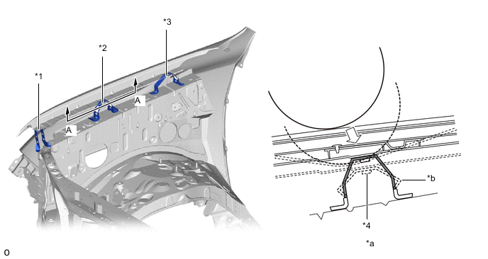
*1 Fender Apron Reinforcement Plate *2 Front Fender Apron Reinforcement Rear *3 Front Fender Apron Reinforcement *4 Front Fender Apron Reinforcement Rear (After Impact Absorption) *a A - A Cross Section *b Fold Point -
A flexible material is used for the front fender main seal. Also, the front fender main seal is structured to slide itself between other components as an impact load is applied to it. Therefore, the reaction force applied by the front fender main seal during a collision with a pedestrian is reduced, with the aim of reducing the predicted impact to the pedestrian's head.
*1 Front Fender Main Seal *2 Front Fender Main Seal (After Collision) *a A - A Cross Section *b Slide between Components -
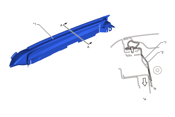
The cowl top ventilator louver is structured to be easily broken during a collision with a pedestrian's head. Also, the thickness of the sheets differs to control deformation during a collision. Therefore, the cowl louver maintains the necessary rigidity, with the aim of reducing the predicted impact to the pedestrian's head.
*1 Cowl Top Ventilator Louver - - *a A - A Cross Section *b Fold Point *c After Impact Absorption *d Low Thickness *e High Thickness - - -
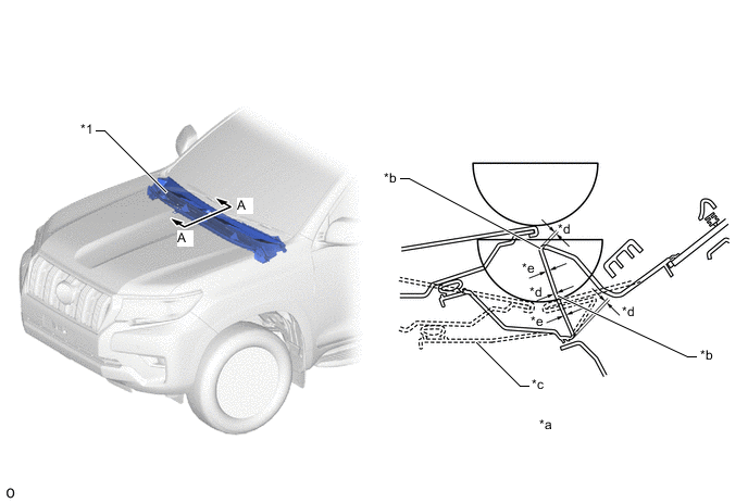
By locating the windshield wiper motor on the lower part of the wiper link, the stroke to reduce impact energy from the top of the hood is ensured.
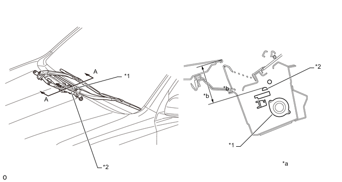
*1 Windshield Wiper Motor *2 Windshield Wiper Link *a A - A Cross Section *b Stroke Space -
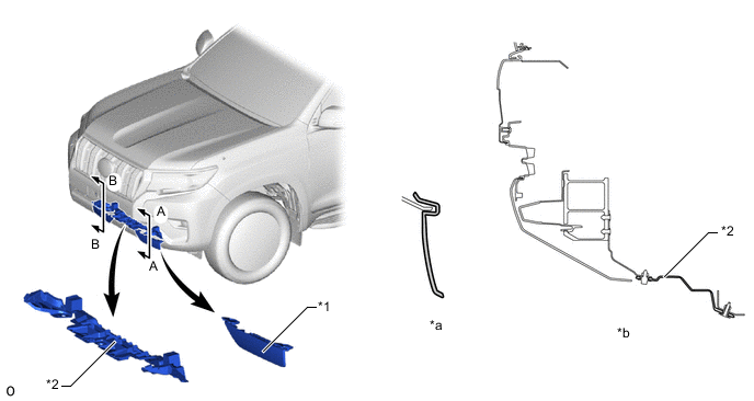
A front bumper absorber lower is provided in front of the front bumper reinforcement sub-assembly to form a structure which reduces the impact to the pedestrian whose lower leg struck the bumper.
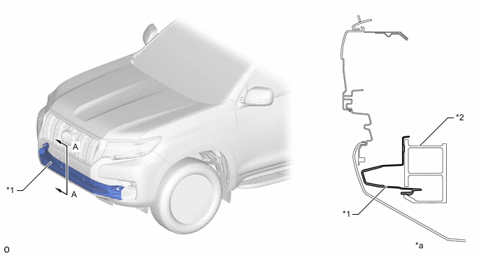
*1 Front Bumper Absorber Lower *2 Front Bumper Reinforcement Sub-assembly *a A - A Cross Section - -
-
-
Aerodynamics
-
A front wheel opening extension pad No. 1 and rocker panel molding protector No. 1 are provided, enhancing aerodynamic characteristics by adjusting the airflow to the tires and the wheelhouse section.
Figure 1. Front Wheel Opening Extension Pad No. 1/ Rocker Panel Molding Protector No. 1 (The illustration shown is an example only.)
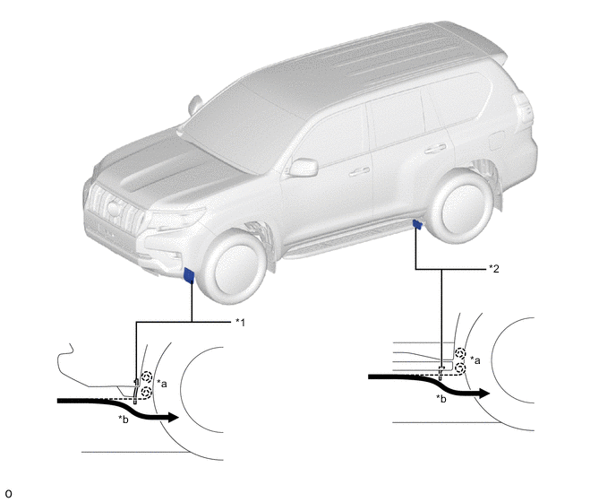
*1 Front Wheel Opening Extension Pad No. 1 *2 Rocker Panel Molding Protector No. 1 *a Air Flow without Front Wheel Opening Extension Pad No. 1 *b Straightening Air Current -
A front spoiler is provided, enhancing aerodynamic characteristics by adjusting the underfloor airflow (on models for Europe and destination packages for South Africa only).
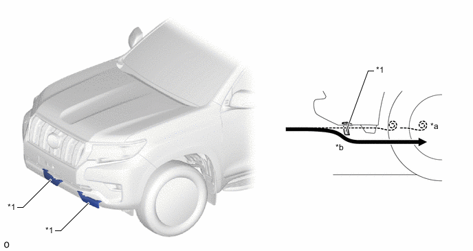
*1 Front Spoiler - - *a Turbulent Flow *b Straightening Air Current -
A rear bumper protector is provided to enhance aerodynamic characteristics by adjusting the airflow without sending it from the rear section of the rear tires toward the rear bumper.
Figure 2. Rear Bumper Protector (The illustration shown is an example only.)
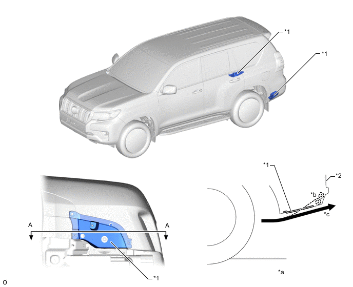
*1 Rear Bumper Protector *2 Rear Bumper *a A - A Cross Section *b Air Flow without Rear Bumper Protector *c Straightening Air Current - - -
A rear spoiler is provided to enhance aerodynamic characteristics by suppressing the turbulence of airflow and by making the air flow rearward.
Figure 3. Rear Spoiler (The illustration shown is an example only.)
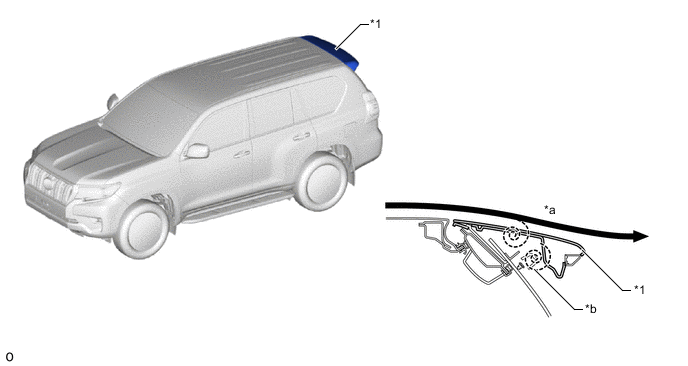
*1 Rear Spoiler - - *a Straightening Air Current *b Air Flow without Rear Spoiler -
A radiator side deflector is provided to enhance aerodynamic characteristics by reducing vortices in air flowing from the radiator grille.
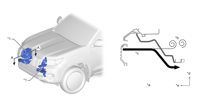
*1 Radiator Side Deflector - - *a A - A Cross Section *b Air Flow without Radiator Side Deflector *c Straightening Air Current *d Outside *e Front Side - - -
An aero stabilizing fin is provided on the outer rear view mirror assembly and a type of aerodynamic technology known as a vortex generator is used for the fin. Small vortices are purposely generated in the airflow to push the vehicle from the left and right sides, achieving excellent operation stability.
Figure 4. Aero Stabilizing Fin (The illustration shown is an example only.)
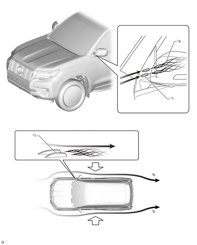
*1 Aero Stabilizing Fin - - *a Generated Vortex *b Main Airflow -
An aero stabilizing fin is provided on the lens surface of the rear combination light assembly and a type of aerodynamic technology known as a vortex generator is used for the fin. Small vortices are purposely generated in the airflow to push the vehicle from the left and right sides, achieving excellent operation stability.
*1 Aero Stabilizing Fin - - *a Generated Vortex - -
-
-
-
CONSTRUCTION
-
High-tensile Strength Steel
-
High-tensile strength steel and ultra high-tensile strength steel are used in order to achieve excellent body rigidity and a lightweight body.
Figure 5. 5-door Models
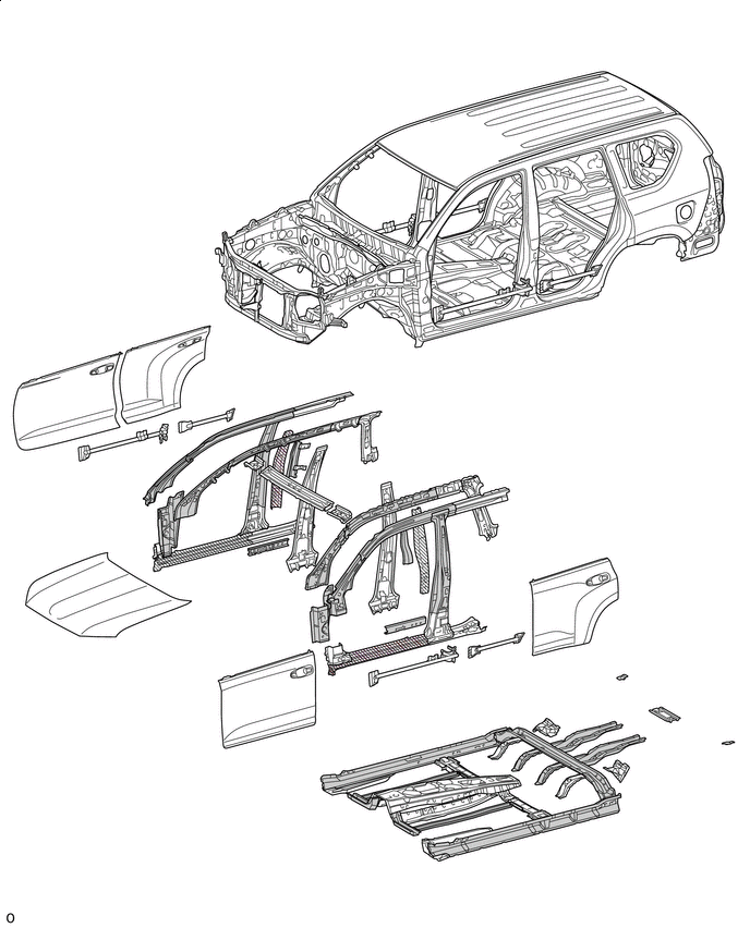

High-tensile Strength Steel 
Ultra High-tensile Strength Steel Figure 6. 3-door Models
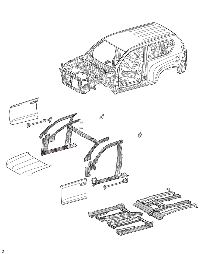
High-tensile Strength Steel Ultra High-tensile Strength Steel
-
-
Anti-corrosion Sheet Steel
-
Anti-corrosion sheet steel is used as in the following illustration:
Figure 7. 5-door Models
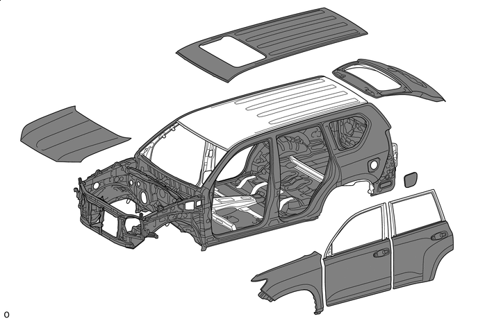
Anti-corrosion Sheet Steel - - Figure 8. 3-door Models
Anti-corrosion Sheet Steel - -
-
-
Anti-chipping Application and Rust-resistant Performance
-
A large resin rocker panel molding is used. Mold-in-color is used for the rocker panel molding on 5-door models. An arch protector is used to protect the arch portion of the rear wheelhouse. Also, anti-chipping tape is used on the rocker panel molding on 3-door models. These features achieve a high level of chip resistance.
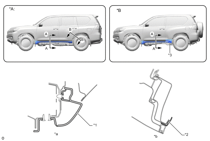
*A 5-door Models *B 3-door Models *1 Rocker Panel Molding *2 Arch Protector *3 Anti-chipping Tape - - *a A - A Cross Section *b B - B Cross Section -
On models with a side step, a side step protects the paint on the outer panels from flying stones and road debris.
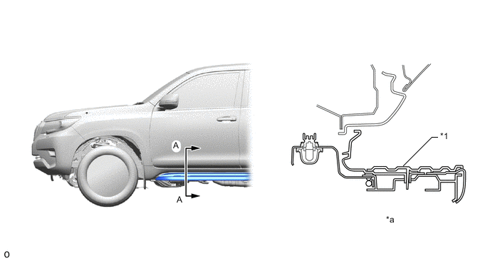
*1 Side Step - - *a A - A Cross Section - - -
On models without a side step, Polyvinyl Chloride (PVC) anti-chipping coating is applied to the door panels to protect the paint on the outer panels from flying stones and road debris.
-
Soft anti-chipping primer is applied to the front of the hood to help prevent rust.
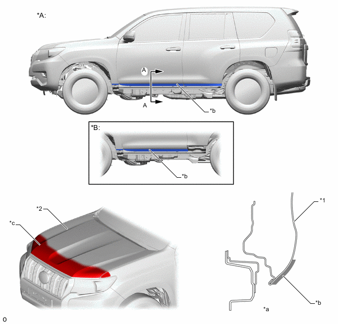
*A 5-door Models *B 3-door Models *1 Door Panel *2 Hood *a A - A Cross Section *b PVC Anti-chipping Coating *c Soft Anti-chipping Primer - - -
Wax is applied to edge of the door lower portion, door hinge and fuel filler lid hinge to improve rust-resistant performance. Sealer is applied to hemmed portions of the hood panel and door panels.
-
Under coating is applied to underside of the body, inside the wheel housing and other parts that are susceptible to stone chipping damage, thus improving the rust-resistant performance of these areas.
Figure 9. Under Coating (The illustration shown is an example only.)
*A 3-door Models - - *1 Edge Seal - - *a Rear Wheel House - - Under Coating Area 
Under Coating Area (Thick Coating)
-
-
Sound Absorbing and Vibration Damping Materials
-
A hood insulator is provided on the rear of the hood panel. Provision of air layers achieves excellent sound insulation performance.
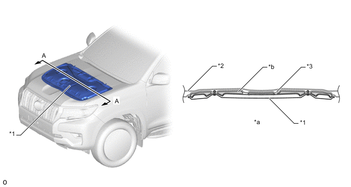
*1 Hood Insulator *2 Hood Panel *3 Hood Inner Panel - - *a A - A Cross Section *b Air Layer -
A dash panel insulator outer is provided. This reduces the engine noise leaking into and out of the cabin.
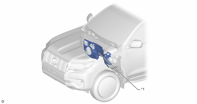
*1 Dash Panel Insulator Outer - - -
A dash panel insulator is provided. This insulates and absorbs the engine noise to reduce the engine noise leaking into the cabin.
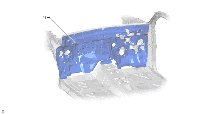
*1 Dash Panel Insulator - - -
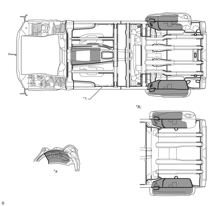
To reduce the amount of road noise, engine noise, and droning sound that enter the cabin, a floor panel is coated with a floor silencer.
Figure 10. Floor Silencer (The illustration shown is an example only.)
*A 3-door Models - - Floor Silencer - - -
All the locations of sound insulation and absorption materials in the cabin have been optimized, thus creating a quiet drive.
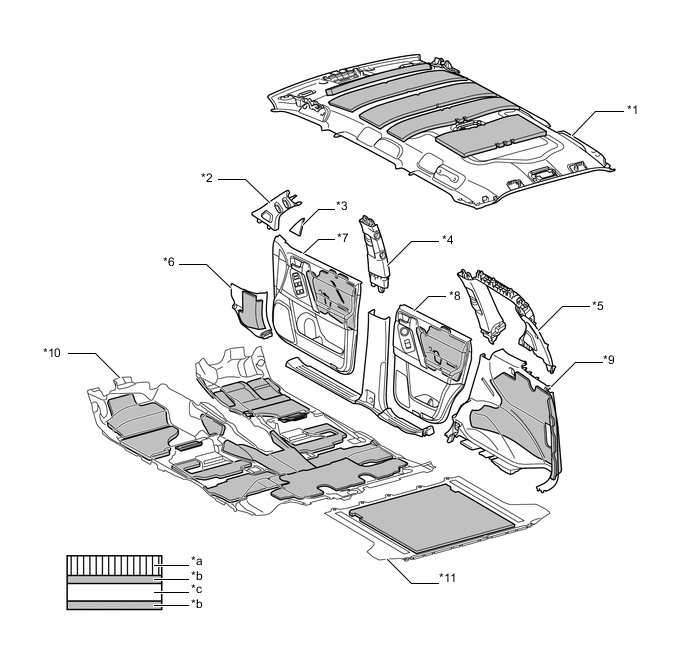
*1 Roof Headlining and Silencer *2 Front Pillar *3 Front Door Lower Frame Bracket Garnish *4 Center Pillar *5 Quarter Trim and Silencer *6 Cowl Side Trim and Silencer *7 Front Door Trim and Silencer *8 Rear Door Trim and Silencer *9 Deck Side Trim and Silencer *10 Floor Carpet and Silencer *11 Rear Floor Carpet and Silencer - - *a Velour (Needle-punched Nonwoven) *b Insulation Layer *c Absorption Layer - - -
A foam type sound insulation material is used in the body frame profile, thus reducing the various noises which intrude from the outside of the vehicle to the inside of the cabin.
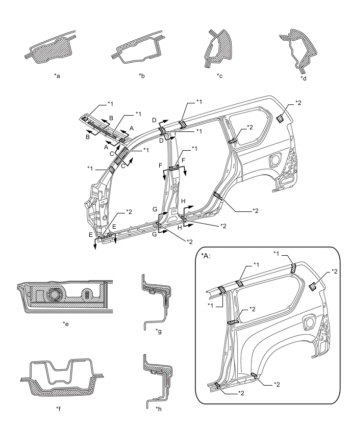
*A 3-door Models - - *1 Foamed Material *2 Solid Foamed Material *a A - A Cross Section *b B - B Cross Section *c C - C Cross Section *d D - D Cross Section *e E - E Cross Section *f F - F Cross Section *g G - G Cross Section *h H - H Cross Section -
On models with acoustic layer laminated windshield glass, an acoustic layer laminated windshield is provided to reduce engine noise and road noise entering the cabin.
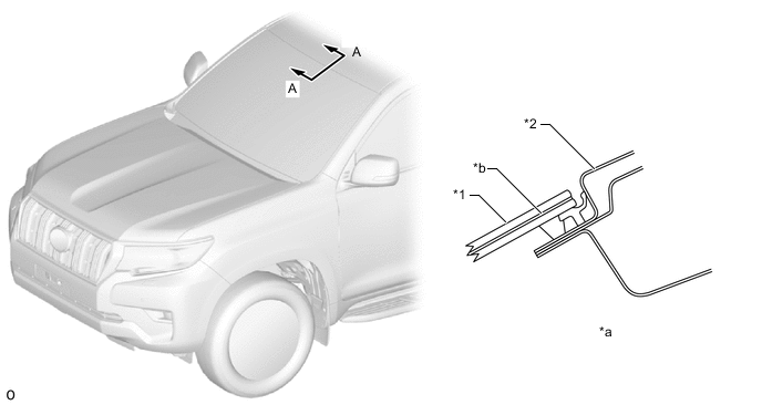
*1 Windshield Glass *2 Roof Panel *a A - A Cross Section *b Acoustic Layer -
A reduction in level differences in the windshield glass molding and the rain gutter molding enhances wind noise reduction.
*1 Windshield Glass *2 Roof Panel *3 Windshield Glass Molding *4 Rain Gutter Molding *5 Side Panel Outer - - *a A - A Cross Section *b B - B Cross Section *c Minimal Level Difference - - -
A front bumper cover lower and front spoiler* are provided and the underfloor airflow is adjusted to enhance wind noise reduction.
-
*: Models for Europe and destination packages for South Africa only
*1 Front Spoiler *2 Front Bumper Cover Lower *a A - A Cross Section *b B - B Cross Section -
-
-
Parts with Low Repair Cost
-
A crush box structure is used to reduce body deformation during minor collisions. A structure with screw connections is provided for the front bumper extension sub-assembly No. 2 (crush box) to enable easy removal and installation, achieving simpler servicing operation and repair cost reduction.
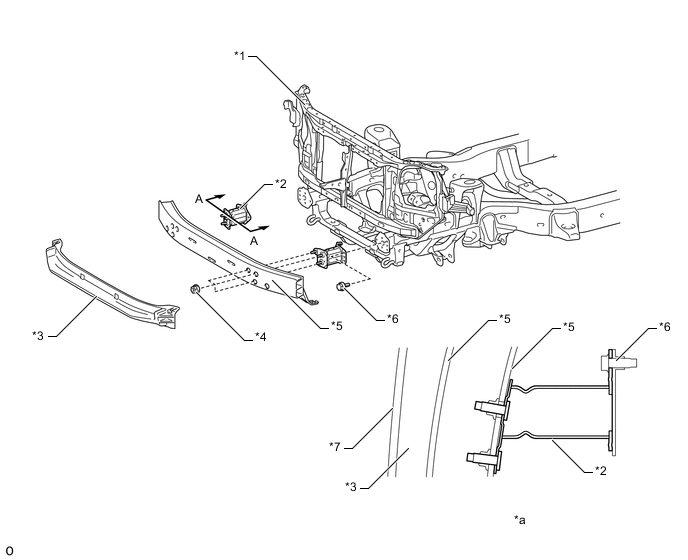
*1 Radiator Support Sub-assembly *2 Front Bumper Extension Sub-assembly No. 2 *3 Front Bumper Absorber Lower *4 Nut *5 Front Bumper Reinforcement Sub-assembly *6 Bolt *7 Front Bumper Cover - - *a A - A Cross Section - -
-
-