LIGHTING SYSTEM
-
FUNCTION OF MAIN COMPONENTS
-
Daytime Running Light System (Models with Daytime Running Light System)
Component Function Main Body ECU (Multiplex Network Body ECU)
-
The main body ECU (multiplex Network Body ECU) receives various signals and illuminates the low beam headlights, taillights, clearance lights and license plate lights.*1
-
The main body ECU receives various signals and illuminates the daytime running light.*2
Headlight Dimmer Switch Assembly Light Control Switch The light control switch outputs a light control signal and transmits it to the main body ECU (multiplex Network Body ECU). ECM The ECM outputs an engine speed signal and transmits it to the main body ECU (multiplex Network Body ECU).
-
*:1 Models with halogen headlight
-
*:2 Models with Light Emitting Diode (LED) headlight
-
-
Automatic Light Control System (Models with Automatic Light Control System)
Component Function Main Body ECU (Multiplex Network Body ECU)
-
Various signals and illuminates the taillights, clearance lights and license plate lights.
-
Sends the illumination signals of headlights (RH side) to the No. 1 headlamp ECU sub-assembly LH.
No. 1 Headlamp ECU Sub-assembly LH illuminates the headlights (LH side) and transmits the illumination signals of headlights (RH side) to the No. 1 headlamp ECU sub-assembly LH. No. 1 Headlamp ECU Sub-assembly RH illuminates the headlights (RH side). Headlight Dimmer Switch Assembly Light Control Switch The light control switch transmits an AUTO position signal to the main body ECU (multiplex Network Body ECU). Light Control Sensor The light control sensor detects the ambient light level. -
-
LED Headlight System (Models with LED Headlight System)
Component Function Main Body ECU (Multiplex Network Body ECU) The main body ECU (multiplex Network Body ECU) receives various signals and transmits it to the No. 1 headlamp ECU sub-assembly LH. No. 1 Headlamp ECU Sub-assembly LH illuminates the headlights (LH side) and transmits the illumination signals of headlights (RH side) to the No. 1 headlamp ECU sub-assembly LH. No. 1 Headlamp ECU Sub-assembly RH illuminates the headlights (RH side). Headlight Dimmer Switch Assembly Light Control Switch The light control switch transmits a HEAD position signal to the main body ECU (multiplex Network Body ECU). -
Automatic Headlight Beam Level Control System (Models with Automatic Headlight Beam Level Control System)
Component Function No. 1 Headlamp ECU Sub-assembly LH
-
Receives various signals and controls the headlight levelingmotor LH.
-
Sends the headlight leveling motor operation signals to the No. 1 headlamp ECU sub-assembly RH.
No. 1 Headlamp ECU Sub-assembly RH Controls the headlight leveling motor RH according to control signals from the No. 1 headlamp ECU sub-assembly LH. Headlight Leveling Motor LH/RH
-
Based on the signals received from the No. 1 headlamp ECU sub-assembly LH/RH, the motors move the reflectors in the headlights.
-
Uses a step motor to precisely regulate the angle of the reflectors.
Height Control Sensor Sub-assembly
-
Detects vehicle height value and transmits a signal to the absorber control ECU.*1
-
Detects vehicle height value and transmits a signal to the No. 1 headlamp ECU sub-assembly LH.*2
Skid Control ECU Sends the vehicle speed signal to the No. 1 headlamp ECU sub-assembly LH. ECM Sends the engine running status signal to the No. 1 headlamp ECU sub-assembly LH. Main Body ECU (Multiplex Network Body ECU) Receives a light control signal and transmits it to the No. 1 headlamp ECU sub-assembly LH. Combination Meter Assembly Headlight Leveling Indicator Light If the system malfunctions, the meter ECU alerts the driver by the headlight leveling indicator light in accordance with the signal from the No. 1 headlamp ECU sub-assembly LH. *1: Models with rear air suspension system
*2: Models without rear air suspension system
-
-
Emergency Brake Signal (Models with Emergency Brake Signal)
Component Function Skid Control ECU
-
Manages signals from each sensor and sends the operation signal of the emergency brake signal to the stop light control ECU assembly.*1
-
Manages signals from each sensor and sends the operation signal of the emergency brake signal to the combination meter assembly.*2
Yaw Rate Sensor Detects vehicle acceleration and sends the information to the skid control ECU. Speed Sensor Detects the wheel speed of each of the 4 wheels. Stop Light Switch Assembly Detects the brake pedal depressing signal. Hazard Warning Signal Switch Assembly Sends the operation signal of the hazard warning light to the skid control ECU and the hazard warning light. Stop Light Control ECU Assembly*1 The stop light and high mount stop light are made to blink in accordance with the hazard warning light and the operation signal of the emergency brake signal from the skid control ECU. Rear Combination Light Assembly*1 Stop Light Blinks when a signal is received from the stop light control ECU assembly. High Mount Stop Light*1 Hazard Warning Light*2 Blinks when a signal is received from the combination meter assembly.*2 Combination Meter Assembly*2 Receives the emergency brake signal and controls the hazard warning lights. *1: Models with 5L-E engine
*2: Except models with 5L-E engine
-
-
Welcome Light Illumination Control System (Models with Welcome Light Illumination Control System)
Component Function Main Body ECU (Multiplex Network Body ECU) The main body ECU (multiplex Network Body ECU) receives various signals and illuminates the tallights, clearance lights, and license plate lights. Headlight Dimmer Switch Assembly Light Control Switch The light control switch transmits an AUTO position signal to the main body ECU (multiplex Network Body ECU). Light Control Sensor The light control sensor detects the ambient light level. Certification ECU
-
The certification ECU receives door lock/unlock operation request signal and sends it to the main body ECU (multiplex Network Body ECU).
-
Receives the ignition signal and transmits it to the main body ECU (multiplex Network Body ECU).
Door with Motor Lock Asembly Door Lock Position Switch Detects whether a door is locked or unlocked and transmits a signal to the main body ECU (multiplex Network Body ECU). Front Door Handle Assembly Outside LH Touch Sensor Transmits the door unlock request signal to the certification ECU. Lock Sensor Transmits the door lock request signal to the certification ECU. Door Control Receiver Transmits the door lock/unlock request signal to the certification ECU. -
-
Follow Me Home (Models with Follow Me Home)
Component Function Central Gateway ECU (Network Gateway ECU) Relays the signals between the CAN communication lines. Certification ECU (Smart Key ECU Assembly) Sends engine switch condition signals to the main body ECU (multiplex network body ECU). Headlight Dimmer Switch Assembly Light Control Switch Sends the light control switch position signal to the main body ECU (multiplex network body ECU). No. 1 Headlamp ECU Sub-assembly LH Supplies power to the headlights. No. 1 Headlamp ECU Sub-assembly RH Main Body ECU (Multiplex Network Body ECU) Receives various signals and sends it to the No. 1 headlamp ECU sub-assembly LH. -
Automatic High Beam System (Models with Automatic High Beam System)
Component Function Automatic High Beam Sensor The automatic high beam sensor determines when to turn the high beams on and off after identifying the lights of oncoming vehicles, preceding vehicles and other lights from the picture information of its camera sensor. Then, it sends high beam request signals to the No. 1 headlamp ECU sub-assembly LH via CAN communication line. Camera Heater (Forward Recognition Hood with Heater Sub-assembly)
-
The camera heater is heated according to signals from the forward recognition camera.
-
Control is performed by the forward recognition camera to supply electric current and heat the heater, preventing the windshield glass in front of the forward recognition camera from fogging up.
Forward Recognition Camera
-
Determines when to turn the high beams on and off after identifying the lights of oncoming vehicles, preceding vehicles and other lights from the picture information of its camera sensor. Then, the sensor sends high beam request signals to the main body ECU (multiplex network body ECU).
-
Controls the supply of electric current to the camera heater when the ambient temperature is low.
No. 1 Headlamp ECU Sub-assembly LH Illuminates the headlights (LH side) and transmits the illumination signals of headlights (RH side) to the No. 1 headlamp ECU sub-assembly LH. No. 1 Headlamp ECU Sub-assembly RH illuminates the headlights (RH side). Skid Control ECU Sends the vehicle speed signal to the No. 1 headlamp ECU sub-assembly LH. ECM The ECM outputs a signal to indicate that the shift lever is in R. Based on this signal, the automatic high beam sensor determines the direction of vehicle movement. Headlight Dimmer Switch Light Control Switch The light control switch transmits AUTO position signal to the main body ECU (multiplex Network Body ECU). Dimmer Switch The dimmer switch transmits high beam position signal to the main body ECU (multiplex Network Body ECU). Automatic Light Control Sensor The automatic light control sensor detects the ambient light level and transmits it to the main body ECU (multiplex Network Body ECU). Combination Meter Assembly Automatic High Beam Indicator Light The automatic high beam indicator light illuminates to inform the driver when the automatic high beam system is activated. Headlight High Beam Indicator Light The headlight high beam indicator light illuminates to inform the driver when the high beams are on. Multi-information Display The multi-information display displays a warning message to inform the driver when the No. 1 headlamp ECU sub-assembly detects malfunction in this system. -
-
-
OPERATING CONDITION
-
Daytime Running Light System
-
Daytime running light system is enabled when the conditions given below are met:
Condition Ignition switch is ON. Light control switch OFF*1 or AUTO*2 position (when the taillights are is not being controlled by the automatic light control). Engine is running. Parking brake is not engaged. *1: Models with light control switch (off position)
*2: Models with light control switch (AUTO position)
-
-
Light Automatic Turn-off System
-
The light automatic turn-off system performs when the following conditions are met:
Function Destination Light Control Switch Position Condition Without Turn-off Delay ALL Except OFF All lights will be turned off if the following condition is met while the lights (headlights, front fog lights*1, rear fog lights*2 and taillights) are turned on:
-
The ignition switch is turned from ON to off and the driver door is open.
Europe AUTO All lights will be turned off if the following condition is met while the lights (headlights, front fog lights*1, rear fog lights*2 and taillights) are turned on:
-
The ignition switch is turned from ON to off and any of all doors, back door and glass hatch is open.
HEAD or TAIL The headlights and front fog lights will be turned off if the following condition is met while the lights (headlights, front fog lights*1, rear fog lights*2 and taillights) are turned on:
-
The ignition switch is turned from ON to off.
With Turn-off Delay Europe AUTO All lights will be turned off after 30 seconds if the following condition is met while the lights (headlights, front fog lights*1, rear fog lights*2 and taillights) are turned on:
-
The ignition switch is turned from ON to off and any of all doors, back door and glass hatch is open.
HEAD or TAIL The headlights and front fog lights will be turned off if the following condition is met while the lights (headlights, front fog lights*1, rear fog lights*2 and taillights) are turned on:
-
The ignition switch is turned from ON to off.
Except Europe AUTO or TAIL All lights will be turned off if the following condition is met while the taillights are turned on:
-
The ignition switch is turned from ON to off and the driver door is open.
AUTO or HEAD All lights will be turned off after 30 seconds if the following condition is met while the headlights are turned on:
-
The ignition switch is turned from ON to off and any of all doors, back door and glass hatch is open and closed.
*1: Models with front fog light
*2: Models with rear fog light
-
-
-
Follow Me Home
-
The follow me home system operates if the lever of the headlight dimmer switch is pulled and released when both of the following conditions are met:
Condition engine switch is off The headlight dimmer switch is in the AUTO or off* position. *: Models with light control switch (off position)
-
-
Automatic High Beam System
Function Operation Condition Active When all of the following conditions are met, the automatic high beam system is activated and the automatic high beam indicator light turns on:
-
The engine switch is on (IG).
-
The light control switch (headlight dimmer switch assembly) is in the AUTO or head position and the low beam headlights are on.
-
The dimmer switch (headlight dimmer switch assembly) is in the high beam position.
-
The automatic high beam switch is on.
-
The shift lever is in any position other than R.
High Beams On When all of the following conditions are met, the automatic high beam system turns on the high beams after a short delay:
-
Vehicle speed is more than approximately 40 km/h (25 mph)*1.
-
Vehicle speed is more than approximately 30 km/h (19 mph)*2.
-
The area in front of the vehicle is dark.
-
No oncoming vehicles are present with the headlights on.
-
No preceding vehicles are present with the taillights on.
-
Few streetlights are present along the street ahead.
High Beams Off When any of the following conditions is met, the automatic high beam system turns off the high beams after a short delay:
-
Vehicle speed is less than approximately 30 km/h (19 mph)*1.
-
Vehicle speed is less than approximately 25 km/h (16 mph)*2.
-
The area in front of the vehicle is not dark.
-
An oncoming vehicle with headlights on is detected.
-
A preceding vehicle with taillights on is detected.
-
Several streetlights are present along the street ahead.
*1: Models for Europe
*2: Except models for Europe
-
-
Welcome Light Illumination System
-
The welcome light illumination system operates as follows:
Function Operation Condition System Activation When all of the following conditions are met, the welcome light illumination system operates.
-
The engine switch is off.
-
The light control switch is in the AUTO position.
-
Any door has been unlocked by wireless unlock function.
-
All doors are closed.
Light Turn-on The clearance lights, taillights and license plate lights turns on for 15 seconds when the wireless door unlock operation or the entry door unlock operation is being used. Light Turn-off After the light is illuminated, the clearance lights, taillights and license platelights are turned off when either of the following conditions is met before 15 seconds have elapsed.
-
The engine switch is on (IG).
-
The light control switch is in any position except the AUTO position.
-
Wireless door lock is performed.
-
Entry door lock is performed.
-
-
-
-
FUNCTION
-
Light Emitting Diode (LED) Headlight System
-
The LED headlight system consists of LEDs and light control ECUs.
-
A fail-safe function is provided when a problem occurs in the headlight system.
-
-
Automatic Headlight Beam Level Control System
-
The automatic headlight beam level control system mainly consists of the No. 1 headlamp ECU sub-assembly LH, rear height control sensor, and 2 headlight leveling motors.
-
The No. 1 headlamp ECU sub-assembly calculates changes in the vehicle posture based on the signals from the height control sensor sub-assembly.
-
The ECU controls the headlight leveling motor based on this information in order to change the headlight reflector angle.
-
Initial Set Control
-
When the engine is started, the No. 1 headlamp ECU sub-assembly drives the headlight leveling motor, moves the headlight reflector to the lower limit position and returns it to the proper position. The No. 1 headlamp ECU sub-assembly thus assesses the position of the headlight for reference control.
-
-
-
Welcome Light Illumination System
-
The welcome light illumination system operates the clearance lights, taillights and license plate lights in conjunction with the locking and unlocking of the doors, ensuring nighttime usability.
-
The welcome light illumination control function can be turned on and off using the customization function. For details, refer to the Repair Manual.
-
-
Automatic High Beam System
-
When passing an oncoming vehicle:
-
The automatic high beam system turns off the high beams before an oncoming vehicle comes within approximately 655 m (2149 ft.).
-
When an oncoming vehicle passes out of camera sensor range, the automatic high beam system turns the high beams on after a short delay.
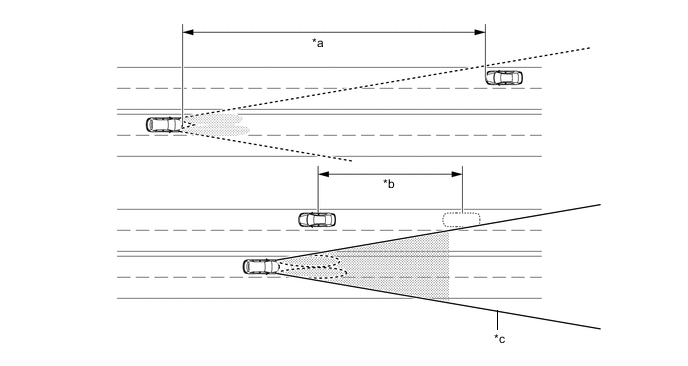
*a 655 m (2149 ft.) *b Delay *c Camera Sensor Angle - - Tech Tips
-
The detection distance varies depending on detected objects.
-
The timing of turning on and off the high beams varies depending on the intensity of oncoming (and preceding) vehicle lights.
-
-
When passing a preceding vehicle:
-
When approaching a preceding vehicle, the automatic high beam system turns off the high beams approximately 458 m (1503 ft.) before reaching it.
-
When a preceding vehicle passes out of camera sensor range, the automatic high beam system turns the high beams on after a short delay.
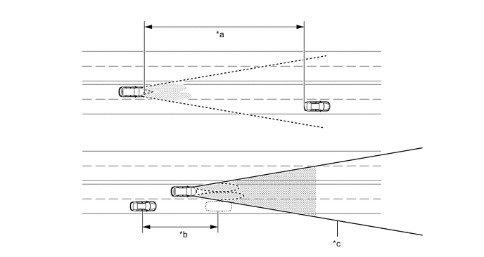
*a 458 m (1503 ft.) *b Delay *c Camera Sensor Angle - - Tech Tips
The timing of turning on and off the high beams varies depending on the intensity of the preceding vehicle lights.
-
-
-
-
CONSTRUCTION
-
No. 1 Headlamp ECU Sub-assembly LH
-
The No. 1 headlamp ECU sub-assembly LH and RH illuminate the LED used as a light source for the low beam headlights and high beam headlights. When the low beam headlights or high beam headlights are illuminated, a constant current flows to the LED to instantly stabilize the headlights. Also, changes in the LED current due to fluctuations in the voltage are reduced to prevent the lights from flickering.
-
The No. 1 headlamp ECU sub-assembly LH controls the automatic headlight beam level control system.
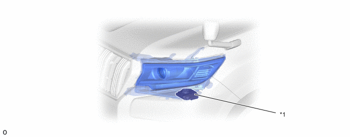
*1 No. 1 Headlamp ECU Sub-assembly LH - - -
If malfunctions occur in an LED headlight system, the No. 1 headlamp ECU sub-assembly transmits fail signals to the combination meter assembly to warn the driver.
-
The combination meter assembly warns the driver by indicating a message on the multi-information display*1, sounding the buzzer and illuminating the headlight warning light and the master warning light*1 when signals are received from the No. 1 Headlamp ECU Sub-assembly LH.
-
*1: Models with optitron display type combination meter assembly
-
*2: Models with analog display type combination meter assembly with segment display type multi-information display (except models with 5L-E engine)
Figure 1. Optitron Display Type Combination Meter Assembly
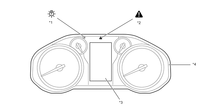
*1 Headlight Warning Light *2 Master Warning Light *3 Multi-information Display *4 Combination Meter Assembly Figure 2. Analog Display Type Combination Meter Assembly with Segment Display Type Multi-information Display (Except Models with 5L-E Engine)
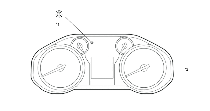
*1 Headlight Warning Light *2 Combination Meter Assembly -
-
-
Forward Recognition Camera
-
The forward recognition camera consists of a Complementary Metal Oxide Semiconductor (CMOS) camera that receives images and a mirror portion that identifies light sources, and judges whether to use high beams or low beams.
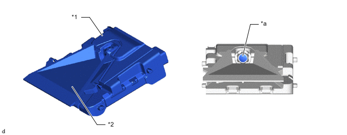
*1 Forward Recognition Camera *2 Camera Heater (Forward Recognition Hood with Heater Sub-assembly) *a Camera Portion - -
-
-
Camera Heater (Forward Recognition Hood with Heater Sub-assembly)
-
The camera heater, which is installed between the forward recognition camera and windshield glass, is heated according to signals from the forward recognition camera in order to prevent the windshield glass on the front of the forward recognition camera from fogging, and also to remove fog buildup. For details, see the PRE-COLLISION SYSTEM section.
-
-
-
OPERATION
-
Emergency Brake Signal (Models with Emergency Brake Signal)
-
Models with 5L-E engine
-
The operating and ending conditions for the emergency brake signal are listed below. When the emergency brake signal operates, the skid control ECU causes the stop light control ECU assembly to blink the stop lights. When the emergency brake signal ends, the skid control ECU causes the stop light control ECU assembly to end the blinking of the stop lights.
Emergency Brake Signal Operating Condition Activates when all of the following conditions are satisfied:
-
The vehicle speed is 55 km/h (34 mph) or more.
-
The system judges from a depression of the brake pedal and a drop in vehicle speed that emergency braking is occurring.
Emergency Brake Signal Ending Conditions Stops the operation when any of the following conditions is met:
-
The system judges from the vehicle's deceleration that no emergency braking is occurring.
-
The hazard warning light is blinking.
-
Driver has released the brake pedal.
-
-
-
Except models with 5L-E engine
-
The operating and ending conditions for the emergency brake signal are listed below. When the emergency brake signal operates, the skid control ECU causes the combination meter assembly to blink the turn signal lights. When the emergency brake signal ends, the skid control ECU causes the combination meter assembly to end the pressed the hazard warning signal switch.
Emergency Brake Signal Operating Condition Activates when all of the following conditions are satisfied:
-
The vehicle speed is 55 km/h (34 mph) or more.
-
The system judges from a depression of the brake pedal and a drop in vehicle speed that emergency braking is occurring.
Emergency Brake Signal Ending Conditions Stops the operation when any of the following conditions is met:
-
The system judges from the vehicle's deceleration that no emergency braking is occurring.
-
Driver has pressed the hazard warning signal switch.
-
Driver has released the brake pedal.
-
-
-
-
-
FAIL-SAFE
-
Light Emitting Diode (LED) Headlight System
-
The No. 1 headlamp ECU sub-assembly executes the fail-safe actions listed below in accordance with the problem that has been detected:
Problem Outline Detection of Abnormal Input Voltage If the voltage input to the No. 1 headlamp ECU sub-assembly deviates from the normal operating voltage (10 V to 16 V), the No. 1 headlamp ECU sub-assembly stops illuminating the headlights. It resumes illuminating the headlights once the voltage reverts to the operating voltage range. However, if the input voltage decreases after the headlights have illuminated, the headlights will remain illuminated until the input voltage is insufficient to light the LEDs. Detection of Abnormal Output (Open Circuit or Short Circuit) If an abnormal condition (open or short) occurs in the voltage that is output by the No. 1 headlamp ECU sub-assembly, the No. 1 headlamp ECU sub-assembly stops illuminating the headlights and will maintain this state until the power is reinstated. Power is reinstated by turning the light control switch from off to on.
-
-
Automatic Headlight Beam Level Control System
-
If the No. 1 headlamp ECU sub-assembly detects a malfunction in the automatic headlight beam level control system, it will take the actions indicated in the table below:
Trouble Area Condition (Fail-safe Control for Automatic Headlight Beam Level Control) Headlight Leveling Indicator Light Speed Sensor Signal Malfunction Continues to control Illuminates Height Control Sensor Signal Malfunction
-
Stops the operation after returning to initial position (fails at higher than initial position).
-
Stops the operation in current condition (fails at lower than initial position).
Illuminates Headlight Leveling Motor Malfunction Normal Side Headlight Leveling Motor:
-
Stops the operation after returning to initial position (fails at higher than initial position).
-
Stops in current condition (fails at lower than initial position).
Illuminates Abnormal Side Headlight Leveling Motor:
-
Stops in its current position.
Illuminates Communication Signal Malfunction Continues to control. Illuminates -
-
-
-
DIAGNOSIS
-
Automatic Headlight Beam Level Control System
-
If the No. 1 headlamp ECU sub-assembly detects a malfunction in the automatic headlight beam level control system, the No. 1 headlamp ECU sub-assembly illuminates the headlight leveling indicator light. At the same time, the Diagnostic Trouble Codes (DTCs) are stored in memory. The DTCs can be read by use of the Global TechStream (GTS). For details, refer to the Repair Manual.
-
-
Automatic High Beam System
-
In order to make system inspections easier to perform, a diagnosis function is used in consideration of serviceability. The Diagnostic Trouble Codes (DTCs) of malfunctions can be read by connecting the Global TechStream (GTS). For details, refer to the Repair Manual.
-
-