AIR CONDITIONING SYSTEM
-
FUNCTION OF MAIN COMPONENTS
-
The air conditioning consists of the following components:
Component Function Front Air Conditioning Control Assembly Allows operation and adjustment of the air conditioning system via switches. Air Conditioning Amplifier Assembly Transmits and receives signals to and from the switches and sensors. Cooler Compressor Assembly Performs suction, compression and discharge of refrigerant gas. Condenser Assembly A Multi-Flow-IV (MF-IV) sub-cool condenser is used to improve heat exchange efficiency. Heater Radiator Unit Sub-assembly A Straight Flow Aluminum-II (SFA-II) heater radiator is used for compactness and high performance. Front Blower Motor with Fan Sub-assembly High magnetic force magnets and ball bearings are used to achieve a compact and lightweight assembly. No. 1 Cooler Evaporator Sub-assembly A Revolutionary super-slim (RS) Structure is used for compactness. No. 1 Front Cooler Thermistor Detects the temperature of the cool air past the No. 1 cooler evaporator sub-assembly and transmits the data to the air conditioning amplifier assembly. Cooler (Ambient Temperature Sensor) Thermistor Detects ambient temperature and outputs it to the air conditioning amplifier assembly via the combination meter assembly. Cooler (Front Room Temperature Sensor) Thermistor*1 Detects room temperature and outputs it to the air conditioning amplifier assembly. Cooler Expansion Valve Sprays the refrigerant in an atomized form. Quick Heater Assembly*2 Consists of a Positive Temperature Coefficient (PTC) element, an aluminum fin, and a brass plate. PTC Heater Relay*2 Adjusts the quick heater in 3 steps. Airmix Damper Servo Sub-assembly Receives the input of temperature setting dial signals via the air conditioning amplifier assembly, operates the motor, and opens and closes the airmix damper. Recirculation Damper Servo Sub-assembly Receives the input of the operation signals from the fresh-air/recirculation selector switch via the air conditioning amplifier assembly, operates the motor, and opens and closes the fresh-air/recirculation damper. Mode Damper Servo Sub-assembly Receives the operation signals from the mode selector switch via the air conditioning amplifier assembly, operates the motor, and opens and closes the mode damper. Clean Air Filter Removes pollen and other particles to provide a comfortable interior space. ECM Receives the signals from the engine coolant temperature sensor and transmits them to the air conditioning amplifier assembly. Air Conditioning Pressure Sensor*3 Mounted on the high-pressure pipe, this sensor controls the cooler compressor assembly. Air Conditioning Pressure Switch*4 Mounted on the high-pressure pipe, this switch controls the cooler compressor assembly. Engine Coolant Temperature Sensor Detects the engine coolant temperature and transmits it to the ECM.
-
*1: Models with automatic air conditioning
-
*2: Models with quick heater assembly
-
*3: Models with 1KD-FTV engine, 1GD-FTV engine or dual air conditioning system.
-
*4: Models with single air conditioning system (without 1KD-FTV engine, 1GD-FTV engine or dual air conditioning system)
-
-
The rear air conditioning consists of the following parts:
Component Function Rear Air Conditioning Control Assembly Allows operation and adjustment of the air conditioning system via switches. Cooler (Rear Room Temperature Sensor) Thermistor Detects the rear room temperature and outputs it to the air conditioning amplifier assembly. Air Conditioning Amplifier Assembly Transmits and receives signals to and from the switches and sensors. Rear Evaporator Sub-assembly A Revolutionary super-slim Structure (RS) is used for compactness. Rear No.1 Cooler Thermistor Detects the temperature of the cool air past the rear evaporator sub-assembly and transmits the data to the air conditioning amplifier assembly. Condenser Assembly A Multi-Flow-IV (MF-IV) sub-cool condenser is used to improve heat exchange efficiency. Heater Radiator Unit Sub-assembly A Straight Flow Aluminum-II (SFA-II) heater radiator is used for compactness and high performance. Rear Blower with Fan Motor Sub-assembly High magnetic force magnets and ball bearings are used to achieve a compact and lightweight assembly. Airmix Damper Servo Sub-assembly Receives temperature setting dial signals via the air conditioning amplifier assembly, operates the motor, and opens and closes the airmix damper. Mode Damper Servo Sub-assembly Receives operation signals from the mode selector switch via the air conditioning amplifier assembly, operates the motor, and opens and closes the mode damper.
-
-
SYSTEM CONTROL
-
The air conditioning system uses following controls:
Control Outline Neural Network Control This control is capable of performing complex control by artificially simulating the information processing method of the nervous system of living organisms in order to establish a complex input/output relationship that is similar to a human brain. Outlet Air Temperature Control Based on the temperature set at the temperature control switch, the neural network control calculates the outlet air temperature based on the input signals from various sensors. The temperature setting for the driver and front passenger is controlled independently in order to provide a separate vehicle interior temperature for the right and left side of the vehicle. Thus, air conditioning control that accommodates occupant preferences has been achieved. Blower Control Controls the blower motor in accordance with the airflow volume that has been calculated by the neural network control based on the input signals from various sensors. Automatically increases the blower level when the defroster is on. Air Outlet Control Automatically switches the air outlets in accordance with the outlet mode that has been calculated by the neural network control based on the input signals from various sensors. Air Inlet Control*1 Automatically controls the air inlet control damper in accordance with the airflow volume that has been calculated by the neural network control. Automatically switches between fresh-air/recirculation in conjunction with the set temperature while the automatic air conditioning is operating. Cooler Compressor Control This control turns off the magnetic clutch of the cooler compressor assembly when the blower motor is turned off at the time the engine coolant temperature is below a predetermined value, an abnormal refrigerant pressure has been input, or the discharge temperature of the evaporator is below a predetermined value. When the DEF mode switch is turned on, the magnetic clutch relay is activated automatically to engage the cooler compressor assembly. Also, when the blower is turned off, and the front defroster switch is turned on, the blower will turn on in the automatic control condition. Turns the air conditioning on automatically by pressing the AUTO button when the blower is on and the air conditioning is off. Rear Window Defogger Control
-
Switches the rear defogger and outer rear view mirror heaters on for 15 minutes when the rear defogger button is pressed.
-
Switches them off if the button is pressed while they are operating.
Windshield Deicer Control*2
-
Switches the windshield deicer on for 15 minutes when the windshield deicer switch is pressed.
-
Switches them off if the switch is pressed while they are operating.
Heated Windshield Defroster Control*3
-
Switches the heated windshield defroster on in accordance with the ambient temperature when the heated windshield defroster switch is pressed.
-
Switches them off if the switch is pressed while they are operating.
Climate Control Seat Control*4 The air conditioning amplifier assembly drives the blower unit provided in the seat back and seat cushion in accordance with the operation of the climate control seat switch. For details, refer to the climate control seat system section. ECO Drive Mode Control*5 Ensures a minimum level of air conditioning control according to the specified conditions of the air conditioning amplifier assembly to improve fuel economy. Self-diagnosis Checks the sensors in accordance with the operation of the air conditioning switches, then displays a Diagnosis Trouble Code (DTC) on the clock to indicate if there is a malfunction or not (sensor check function).
-
*1: Except models for G.C.C. countries
-
*2: Models with windshield deicer
-
*3: Models with heated windshield defroster
-
*4: Models with climate control seat
-
*5: Models with eco mode switch
-
-
Neural Network Control
-
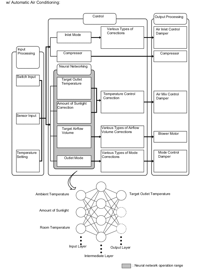
In the previous automatic air conditioning system, the air conditioning amplifier assembly determined the required outlet air temperature and blower air volume in accordance with a calculation formula that had been obtained based on information received from the sensors. However, because the sensors of a person are rather complex, a given temperature is sensed differently, depending on the environment in which the person is situated. For example, a given amount of solar radiation can feel comfortably warm in a cold climate, but extremely uncomfortable in a hot climate. Therefore, as a technique for performing a high level of control, a neural network is used in the automatic air conditioning system. With this technique, the data that has been collected under varying environmental conditions is stored in the air conditioning amplifier assembly, which performs control to provide enhanced air conditioning comfort.
-
The neural network control consists of neurons in an input layer, an intermediate layer and an output layer. The input layer neurons process the input data of the ambient temperature, the amount of sunlight, and the room temperature based on the outputs of the switches and sensors, and output them to the intermediate layer neurons. Based on this data, the intermediate layer neurons adjust the strength of the links among the neurons. The sum of this data is then calculated by the output layer neurons in the form of the required outlet temperature, solar correction, target airflow volume, and outlet mode control volume. Accordingly, the air conditioning amplifier assembly controls the servomotors and blower with fan motor sub-assembly in accordance with the control volumes that have been calculated by the neural network control.
-
-
Quick Heater Control
-
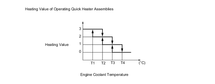
The on/off function of the quick heater assembly is controlled by the air conditioning amplifier assembly in accordance with the engine coolant temperature, engine speed, air mix setting, and electrical load (generator power ratio).
-
For example, the heating value of the operating quick heater assemblies varies depending on the engine coolant temperature as shown in the graph below:
-
-
Viscous Type Power Heater
-
This system complements the conventional heater (heater core) when the engine coolant temperature is low, and accelerates the engine warm up by using the viscous power heater unit driven by the engine. Thus, heater performance improvement in cold conditions is successfully achieved.
-
The power heater, which is located on top of the engine, is driven by a drive belt. Pressing the heater switch assembly or idle up switch provided in the instrument panel engages the magnetic clutch, causing the rotor in the power heater to rotate and the silicon oil to mix. The sheer heat that is thus generated heats the coolant.
-
-
Cool Box Control
-
On models for G.C.C. countries, when the cool box is turned on while the air conditioning system is off and when the air conditioning system is turned off while the cool box is on, the blower motor will be in Lo mode, the outlet will be in DEF mode and the set temperature will be 25°C (77°F). As a result, the cool box can now be turned on whether the air conditioning system is on or off.
-
-
Combustion Type Power Heater
-
Igniting
-
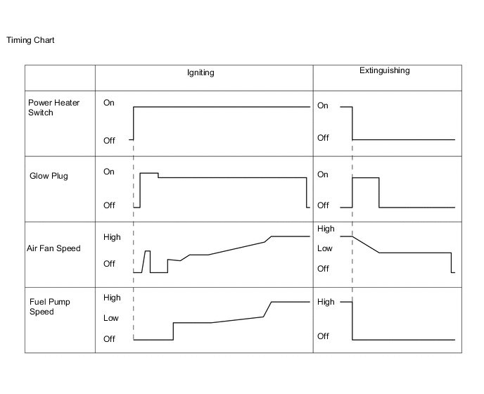
When the engine is operating, turning the heater switch assembly (power heater switch) on causes the air fan to operate for several seconds for verification purposes. Then, the glow plug starts to preheat the combustion chamber. After that, the fuel pump and air fan turn on in order to start low combustion. The fuel pump speed is then increased in steps, and this is accompanied by a gradual increase in the speed of the air fan, thus leading to high combustion.
-
-
Extinguishing
-
When the ignition switch (engine switch*) is turned off or the power heater switch is turned off, the fuel pump stops, causing the combustion to stop. For the purpose of after-purge, current is applied again to the glow plug, and the air fan is activated for several seconds. Then, the entire system comes to a stop.
-
*: Models with entry and start system
-
-
Operating
-
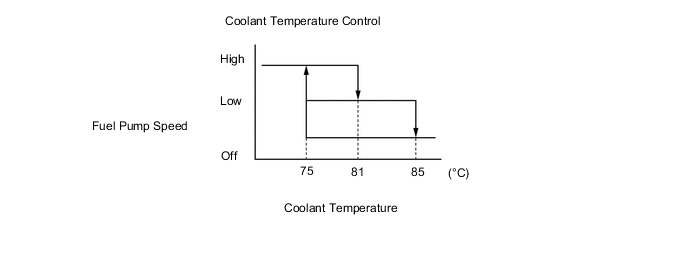
While the system is in operation, it controls the fuel pump speed and switches between high combustion and low combustion, constantly keeping the engine coolant temperature between 75°C (167°F) and 85°C (185°F). If the engine coolant temperature exceeds 85°C (185°F), the fuel pump stops automatically to stop the combustion. Thereafter, when the engine coolant temperature reaches 75°C (167°F) or below, ignition occurs again. The operation of the glow plug, the air fan, and the fuel pump during extinguishing and re-igniting is the same as when these are operated by a switch as mentioned previously.
-
-
Protective Control
-
For self-protection, this system stops if an abnormal condition is detected. Descriptions of the control are indicated below.
Function Control Dry Run Prevention If the temperature detected by the engine coolant temperature sensor or the overheating prevention sensor exceeds 125°C (257°F), the air conditioning amplifier assembly determines that the heater is operating without water and automatically stops the system. Overheating Prevention If the difference in temperature detected by the engine coolant temperature sensor and the overheating prevention sensor exceeds 25°C (77°F), the air conditioning amplifier assembly determines that the flow volume of the water is insufficient and automatically stops the system. Non-ignition or Misfiring Detection If the temperature of the exhaust gas detected by the flame sensor is low, the air conditioning amplifier assembly determines that a non-ignition or a misfiring condition exists and automatically stops the system. Open or Short Circuit Detection If an open or short circuit exists in the sensors or actuators, the air conditioning amplifier assembly automatically stops the system. Air Fan Seizure Detection If the air fan seizes, the air conditioning amplifier assembly automatically stops the system. -
-
-
ECO Drive Mode Control
-
During ECO drive mode, the air conditioning amplifier assembly restricts the air conditioning system performance under specified conditions, thus improving fuel economy.
-
The ECO drive mode control is activated when the eco mode switch is operated, and then restricts the air conditioning system performance as described below:
Control Outline Inside/Outside Air Switch Control Automatically switches the air inlet port to the internal air circulation mode when the outside air temperature is equal to or higher than a predetermined temperature and reduces the power consumption. Blower Level Control Sets the blower level in AUTO mode lower than normal, and suppresses the power consumption.
-
-
-
CONSTRUCTION
-
Air Conditioning Control Assembly
-
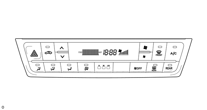
Manual Air Conditioning Control Assembly
-
5 air outlet modes are provided on the control panel on the models with manual air conditioning.
-
-
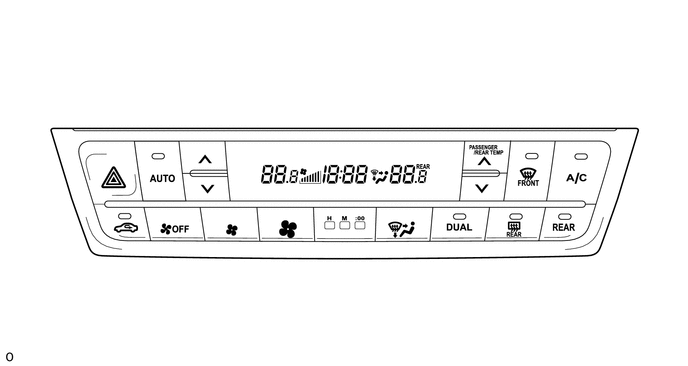
Automatic Air Conditioning Control Assembly
-
An automatic air conditioning control assembly with a Liquid Crystal Display (LCD) is used to ensure excellent visibility.
-
Temperature control can be set independently for the driver and front passenger sides. For this reason, temperature control switches for the driver and front passenger are provided on the air conditioning control assembly.
-
-
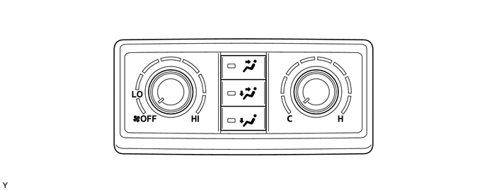
Rear Manual Air Conditioning Control Assembly
-
A rotary switch type rear manual air conditioning control assembly is used, and is located on the rear console panel.
-
-
Rear Automatic Air Conditioning Control Assembly
-
A rear automatic air conditioning control assembly with a Liquid Crystal Display (LCD) is used to ensure excellent visibility.
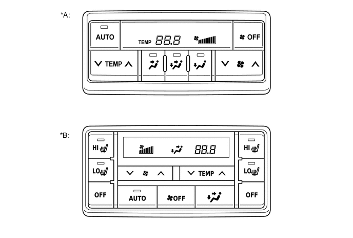
Text in Illustration *A Models without Seat Heater System *B Models with Seat Heater System -
-
-
Air Conditioning Unit
-
The air conditioning unit consists of a No. 1 cooler evaporator sub-assembly, heater radiator unit sub-assembly, servomotors, front No. 1 cooler thermistor, quick heater assembly* and blower with fan motor sub-assembly.
-
*: Models with quick heater assembly
-
-
A semi-central location air conditioning unit, in which the No. 1 cooler evaporator sub-assembly and heater radiator unit sub-assembly are placed in the vehicle's longitudinal direction, is used.
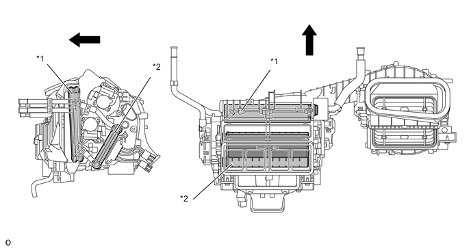
Text in Illustration *1 No. 1 Cooler Evaporator Sub-assembly *2 Heater Radiator Unit Sub-assembly 
Front - -
-
-
No. 1 Cooler Evaporator Sub-assembly
-
A Revolutionary super-slim Structure (RS) evaporator is used. By placing the tanks at the top and the bottom of the No. 1 cooler evaporator sub-assembly and by using a micropore tube construction, the following effects have been achieved:
-
Heat exchanging efficiency is ensured.
-
The temperature distribution is made uniform.
-
The No. 1 cooler evaporator sub-assembly has been made thinner.
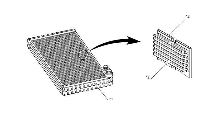
Text in Illustration *1 Tank *2 Micropore Tube *3 Cooling Fin - - -
-
-
Front No. 1 Cooler Thermistor
-
The front No. 1 cooler thermistor detects the temperature of the cool air immediately past the No. 1 cooler evaporator sub-assembly in the form of resistance changes, and outputs it to the air conditioning amplifier assembly.
-
-
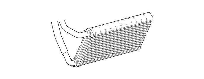
Heater Radiator Unit Sub-assembly
-
This heater radiator unit sub-assembly has been made more compact and performance has been improved by making the core section finer and improving the shapes of the tank section and flow section. Also, the environment has been considered. By using aluminum as the material, the amount of the environmental burden disposal (lead) has been reduced.
-
-
Blower with Fan Motor Sub-assembly
-
The blower with fan motor sub-assembly has a built-in blower controller, and is controlled using duty control performed by the air conditioning amplifier assembly.
-
-
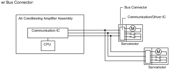
Bus Connector
-
The bus connector has a built-in communication/driver IC, which communicates with each servomotor connector, actuates the servomotor, and has a position detection function. This enables bus communication for the servomotor wire harness to achieve a more lightweight construction and a reduced number of wires.
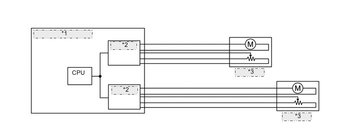
w/o Bus Connector *1 Air Conditioning Amplifier Assembly *2 Driver IC *3 Servomotor
-
-
Servomotor
-
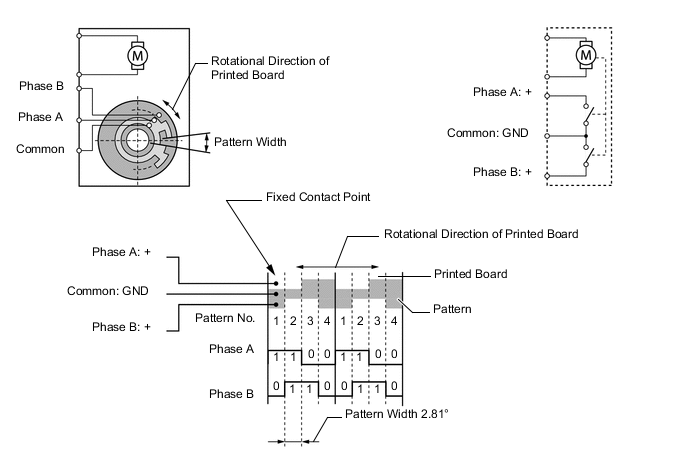
In contrast to the previous type that detects the position by way of a potentiometer voltage, the pulse pattern type servomotor detects the relative position by way of the 2-bit on/off signals.
-
The forward and reverse revolutions of this motor are detected by way of 2 phases, A and B, which output 4 types of patterns. The air conditioning amplifier assembly counts the number of pulse patterns in order to determine the stopped position.
-
-
Quick Heater Assembly
-
The quick heater assembly is located above the heater radiator unit sub-assembly in the air conditioning unit.
-
The quick heater assembly consists of a PTC element, an aluminum fin, and a brass plate. When current is applied to the PTC element, it generates heat to warm the air that passes through the unit.
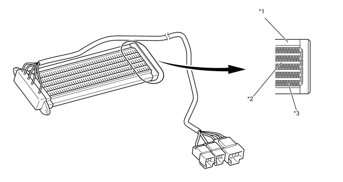
Text in Illustration *1 Brass Plate *2 PTC Element *3 Aluminum Fin - -
-
-
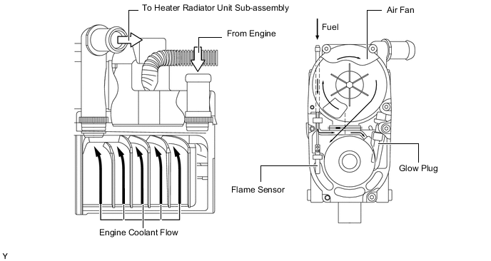
Combustion Type Power Heater Assembly
-
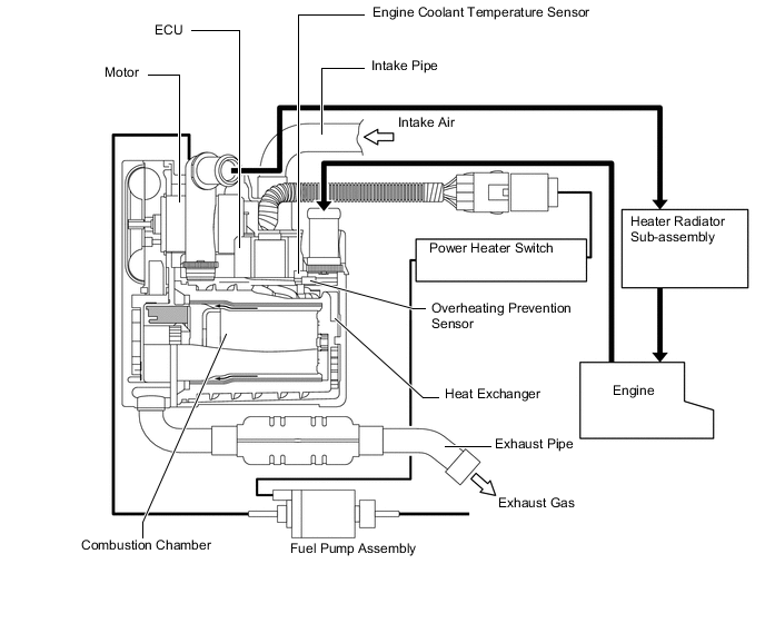
The combustion type power heater assembly consists mainly of a heater exchanger, a glow plug, a motor, an air fan, an ECU, an engine coolant temperature sensor, an overheating prevention sensor, a flame sensor, an intake pipe, an exhaust pipe and a fuel pump.
-
This heater is installed between the engine and heater radiator unit sub-assembly. The engine coolant from the engine flows through the spiral passage around the heat exchanger and flows into the heater radiator unit sub-assembly. At this time, the glow plug ignites the air and fuel in the combustion chamber of the heat exchanger, and the resultant heat of combustion heats the engine coolant.
-
-
Clean Air Filter
-
A pollen removal type clean air filter is used to remove dust, pollen, and other micron particles from air entering from outside the vehicle to provide a comfortable cabin of clean air. The clean air filter is installed in the upper section of the blower fan.
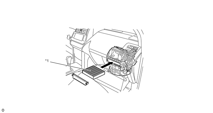
*1 Clean Air Filter - -
-
-
Condenser Assembly
-
A sub-cool condenser is used. This is a multi-flow condenser consisting of 3 portions: a condensing portion, a super-cooling portion and a gas-liquid separator (modulator) all integrated together. This condenser assembly uses a sub-cool cycle for its cooling cycle system to improve heat-exchanging efficiency.
-
In the sub-cool cycle, after the refrigerant passes through the condensing portion of the condenser assembly, both the liquid refrigerant and the gaseous refrigerant that could not be liquefied are cooled again in the super-cooling portion. Thus, the refrigerant is sent to the No. 1 cooler evaporator sub-assembly in an almost completely liquefied state.
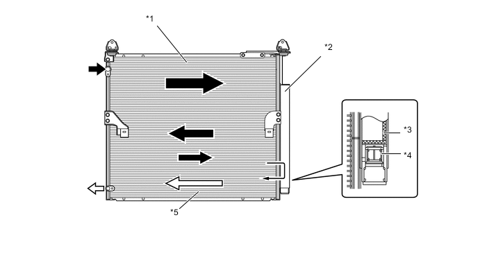
Text in Illustration *1 Condensing Portion *2 Modulator *3 Desiccant *4 Filter *5 Super-cooling Portion - - Gaseous Refrigerant 
Liquid Refrigerant Tech Tips
The point at which the air bubbles disappear in the refrigerant of the sub-cool cycle is lower than the proper amount of refrigerant with which the system must be filled. Therefore, if the system is recharged with refrigerant based on the point at which the air bubbles disappear, the amount of refrigerant would be insufficient. As a result, the cooling performance of the system will be affected. If the system is overcharged with refrigerant, this will also lead to reduced performance. For the proper method of verifying the amount of the refrigerant and to recharge the system with refrigerant, refer to the Repair Manual.
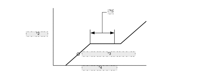
*1 Properly Recharged Amount *2 High Pressure *3 Point at which Bubbles Disappear *4 Amount of Refrigerant
-
-
Cooler Compressor Assembly (Except Models with 1GD-FTV Engine or 2TR-FE Engine)
-
A compact, lightweight, and low-noise 10-cylinder swash plate type cooler compressor (10S17C) is used.
-
-
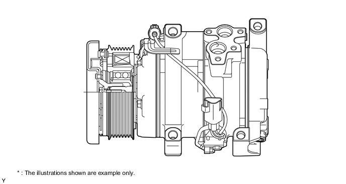
Cooler Compressor Assembly (Models with 2TR-FE Engine or 1GD-FTV Engine)
-
A fixed capacity swash plate type 10SRE18C compressor is used.
-
A rotary valve that intakes refrigerant directly into the cylinder is used, achieving a reduction in refrigerant intake loss.
-
A shaft oil separator that separates compressor oil from the refrigerant is used.
-
Compressor oil, which has been mixed with the refrigerant and circulated in the air conditioning cycle, is separated by the shaft oil separator built into the shaft and accumulated in the compressor.
-
For the shaft oil separator, an oil return passage is located between the cylinder and the lug plate, and refrigerant gas in which a small amount of oil is mixed is sent to the intake chamber. As a result, the oil circulation amount in the air conditioning cycle is reduced.
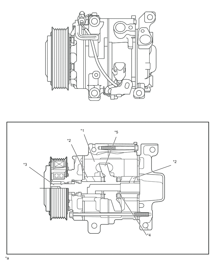
Text in Illustration *1 Piston *2 Rotary Valve *3 Shaft *4 Oil Separator *5 Swash Plate - - *a The illustrations shown are example only. - - -
-
Rotary Valve
-
The rotary valve has a structure where refrigerant passing through the center of the hollow shaft is taken into the compression areas within the cylinder. The intake of refrigerant occurs when the openings of the shaft and cylinder overlap.
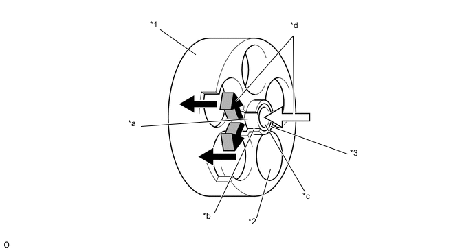
Text in Illustration *1 Cylinder *2 Piston *3 Shaft - - *a Rotary Valve Intake *b Position where Rotary Valve Intake and Cylinder Intake Passage Align *c Cylinder Intake Passage *d Flow of Refrigerant -
-
-
Cooler (Front Room Temperature Sensor) Thermistor
-
The cooler (front room temperature sensor) thermistor detects the front room temperature based on changes in the resistance of its built-in thermistor. This signal is used by the air conditioning amplifier assembly.
-
-
Cooler (Rear Room Temperature Sensor) Thermistor
-
The cooler (rear room temperature sensor) thermistor detects the rear room temperature based on changes in the resistance of its built-in thermistor. This signal is used by the air conditioning amplifier assembly.
-
-
Cooler (Ambient Temperature Sensor) Thermistor
-
The cooler (ambient temperature sensor) thermistor detects the ambient temperature based on changes in the resistance of its built-in thermistor. This signal is used by the air conditioning amplifier assembly.
-
-
Cooler (Solar Sensor) Thermistor
-
The cooler (solar sensor) thermistor detects (in the form of changes in the current that flows through the built-in photo diode) the changes in the amount of sunlight and outputs this sunlight strength signal to the air conditioning amplifier assembly.
-
-
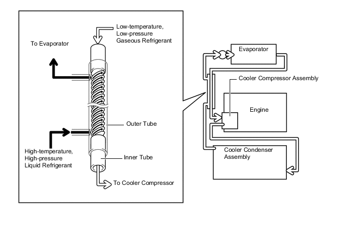
Sub-cool Accelerator Type Tube
-
A sub-cool accelerator type tube is used to enhance air conditioning cooling performance. The tube functions as a heat exchanger by making use of the temperature difference between the gaseous refrigerant and liquid refrigerant.
-
The sub-cool accelerator type tube has a double-pipe construction. Helical grooves are embossed into the outer wall of the inner tube. Low-temperature and low-pressure gaseous refrigerant passes through the inner tube. High-temperature and high-pressure liquid refrigerant circulates between the inner tube and outer tube in the gap created by the grooves. Because of the temperature difference, heat exchange occurs.
-
The high-temperature and high-pressure liquid refrigerant circulates along the helical grooves causing the refrigerant to remain in contact with the outer wall of the inner tube for a longer period of time. This achieves an ample exchange of heat.
-
By lowering the temperature of the refrigerant that has passed through the cooler condenser, more liquid refrigerant is supplied to the evaporator and the evaporator is also kept cooler. This enables an enhanced air conditioning cooling effect.
-
-
Cool Box
-
The cool box consists primarily of a cool box amplifier, an evaporator (for cool box), a cool box blower motor, a cool box switch, and an expansion valve. The connected refrigerant circuit of the front air conditioning cools the cool box.
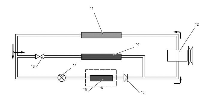
Text in Illustration *1 Condenser Assembly *2 Cooler Compressor Assembly *3 Check Valve *4 No. 1 Cooler Evaporator Sub-assembly *5 No. 1 Cooler Evaporator Sub-assembly No.2 *6 Cool Box *7 Magnetic Valve *8 Cooler Expansion Valve
-
-
-
OPERATION
-
Front Air Conditioning Mode Position and Damper Operation
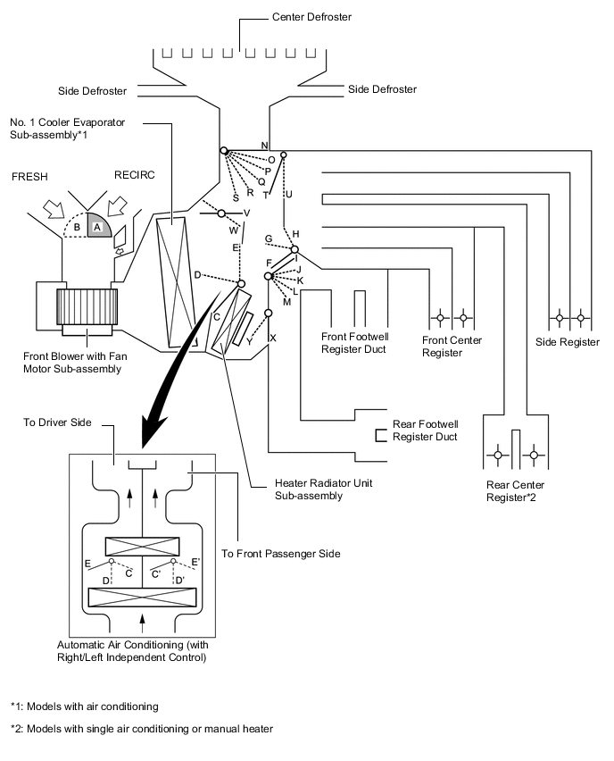
Control Damper Operation Position Damper Position Operation Air Inlet Control Damper FRESH A Brings in fresh air. RECIRC B Recirculates internal air. Air Mix Control Damper MAX COLD to MAX HOT Temp. Setting E - D - C
(E' - D' - C')
Varies the mixture ratio of the cold air and the hot air in order to regulate the temperature continuously from HOT to COLD. Max Cool Damper Max Cool V Open in the MAX COOL position Except Max Cool W Closed in all position except MAX COOL position Max Hot Damper Max Hot Y Open in the MAX HOT position Except Max Hot X Closed in all position except MAX HOT position Mode Control Damper 
DEF H, I, S, U, X Defrosts the windshield through the center defroster, and side defroster. 
FOOT/DEF Max Hot Position H, K, R, T, W, Y Defrosts the windshield through the center defroster, side defroster, front and rear footwell register ducts while air is also blown out from the front and rear center registers and side register. Except Max Hot Position H, M, Q, T, X 
FOOT Max Hot Position H, M, P, T, W, Y Air blows out of the front and rear footwell register duct. In addition, air blows out slightly from the center register, side register, rear center register*, center defroster and side defroster. Except Max Hot Position H, M, O, T, X 
BI-LEVEL Max Hot Position G, L, N, W, Y Air blows out of the front and rear center registers*, side register, and front and rear footwell register ducts. Except Max Hot Position G, L, N, T, X 
FACE Auto Mode F, J, N, T, X Air blows out of the front and rear center registers*, and side register. Manual Mode F, I, N, T, X
-
*: Models with single air conditioning
-
-
Rear Air Conditioning Mode Position and Damper Operation
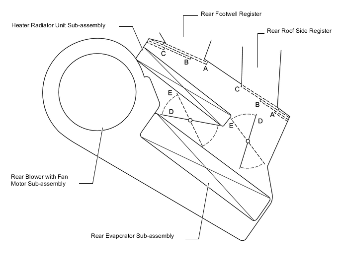
Control Damper Operation Position Damper Position Operation Mode Control Door FACE A Air blows out of the rear roof side register. BI-LEVEL B Air blows out of the rear roof side register and the rear footwell register. FOOT C Air blows out of the rear footwell register. Air Mix Control Damper MAX COLD to MAX HOT Temp. Setting D - E Varies the mixture ratio of the cold air and the hot air in order to regulate the temperature continuously from HOT to COLD. -
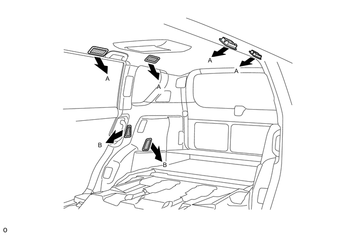
Front Air Outlets and Airflow Volume (Models with Automatic Air Conditioning)
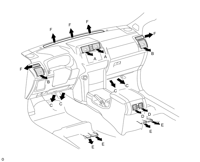
Indication Mode Section A B C D E F Auto Manual Center Side Front Footwell Rear Face*1 Rear Footwell Defroster FACE-U ● ● 
- 
- - FACE-L*2 ● - 


- BI-LEVEL ● ● 

- FOOT ● ● 
FOOT/DEF ● ● DEF - ● - - - - - Tech Tips
*1: Models with single air conditioning
*2: The airflow volume is set to be greater than that of FACE-U mode.
The size of the circle ○ indicates the proportion of airflow volume. The airflow volume from each air outlet is only for reference.
-
Front Air Outlets and Airflow Volume (Models with Manual Air Conditioning or Manual Heater)
Indication Mode A B C D E F Center Side Front Footwell Rear Face* Rear Footwell Defroster FACE - - - BI-LEVEL - FOOT FOOT/DEF DEF - - - - - Tech Tips
*: Models with single air conditioning or manual heater
The size of the circle ○ indicates the proportion of airflow volume. The airflow volume from each air outlet is only for reference.
-
Rear Air Outlets and Airflow Volume
Indication Mode A B FACE - BI-LEVEL FOOT - Tech Tips
The size of the circle ○ indicates the proportion of airflow volume. The airflow volume from each air outlet is only for reference.
-
-
DIAGNOSIS
-
Diagnostic Trouble Code (DTC)
-
The air conditioning amplifier assembly has a self-diagnosis function. The assembly stores any operation failures in the air conditioning system memory in the form of DTCs. For details, refer to the Repair Manual.
-
-
Combustion Type Power Heater
-
If a malfunction occurs in the system, it is possible to access the DTC (Diagnostic Trouble Code) by using a SST (Special Service Tools) that has been designed exclusively for the combustion type power heater. For details, refer to the Repair Manual.
Note
-
When the power heater is turned ON or OFF, some white smoke and a slight odor may be emitted from the exhaust located under the floor. If the power heater is being used under extremely cold conditions, vapor may be visible from the exhaust. This is normal.
-
We recommend not to restart the power heater for 10 minutes after you turn it OFF. Otherwise, a noise may be heard as the heater ignites.
-
Do not turn the power heater ON and OFF repeatedly within 5 minutes intervals as this can shorten the life of the heater components. If the engine is to be turned ON and OFF repeatedly within short intervals (such as when being used for delivery purposes), turn the power heater switch OFF.
-
-
-