PRE-CRASH SAFETY SYSTEM
-
FUNCTION OF MAIN COMPONENTS
Item Function Millimeter Wave Radar Sensor Assembly Radiates millimeter waves forward, uses the reflected millimeter waves for detecting the presence of a vehicle ahead, the vehicle-to-vehicle distance, and the relative speed, and then transmits this information to the driving support ECU assembly. Forward Recognition Camera
-
Acquires a video of the area in front of the vehicle, and performs image processing to recognize obstacles or vehicles ahead, and then transmits this information to the driving support ECU assembly.
-
Operates the camera heater (forward recognition hood with heater sub-assembly) to remove condensation from the part of the windshield in front of the forward recognition camera.*1
Forward Recognition Hood with Heater Sub-assembly*1 Heats the sheet heater in accordance with the signals from the forward recognition camera. Center Airbag Sensor Assembly Deceleration Sensor Detects the lateral/longitudinal deceleration of the vehicle and transmits the signal to the driving support ECU assembly. Yaw Rate Sensor Detects the yaw rate and transmits the signal to the driving support ECU assembly. Steering Angle Sensor Detects the steering direction and angle of the steering wheel and transmits the signal to the driving support ECU assembly. Speed Sensor Detects the wheel speed and transmits signals to the skid control ECU. Park/Neutral Position Switch Assembly Detects the shift lever position and transmits signals to the ECM. Cooler (Ambient Temp. Sensor) Thermistor Detects the ambient temperature and transmits signals to the air conditioning amplifier assembly. Stop Light Switch Assembly Detects the depressing of the brake pedal and transmits signal to the skid control ECU. Stop Light Control ECU Assembly Illuminates the stop lights in accordance with the signals from the stop light switch assembly or skid control ECU. VSC OFF Switch Disables the pre-crash braking and pre-crash brake assist operation when the switch is turned on. The PCS warning light illuminates to show that the pre-crash braking and pre-crash brake assist operation is disabled. The pre-crash warning function can still operate. Steering Pad Switch Assembly Switches the display of multi-information display within combination meter assembly. Skid Control Buzzer Assembly Sounds to warn the driver in accordance with signals from the driving support ECU assembly. Combination Meter Assembly PCS Warning Light
-
Flashes or illuminates to warn the driver in accordance with signals from the driving support ECU assembly.
-
Flashes when the pre-crash safety system is malfunctioning.
-
Illuminates when the pre-crash safety system is not available due to when the pre-crash safety system is turned OFF or pre-crash braking and pre-crash brake assist operation are disabled using the VSC OFF switch.
VSC OFF Indicator Light Illuminates when in VSC OFF mode. Master Warning Light Illuminates to warn the driver in accordance with signals from the driving support ECU assembly when the pre-crash safety system is malfunctioning. Multi-information Display
-
Displays a warning message to inform or warn the driver of the system condition in accordance with signals from the driving support ECU assembly.
-
Displays the pre-crash safety system setting screen.
Meter Buzzer Sounds to warn the driver in accordance with signals from the driving support ECU assembly when the system is malfunctioning. Driving Support ECU Assembly Determines whether a collision is imminent based on the information received from the millimeter wave radar sensor assembly and forward recognition camera. Sends control signals to the skid control ECU assembly, suspension control ECU*2 and ECM when it determines that there is a possibility of a collision or a collision is imminent based on the information received from the millimeter wave radar sensor assembly and forward recognition camera. Skid Control ECU
-
Receives a brake assist standby request signal from the driving support ECU assembly, and switches the brake assist to standby mode. When a master cylinder pressure signal is input, it activates the brake assist.
-
Receives a pre-crash brake request signal from the driving support ECU assembly, and then applies the brakes.
-
Transmits vehicle speed signals to the driving support ECU assembly.
ECM
-
Transmits accelerator pedal position signal and shift position signal to the driving support ECU assembly.
-
Controls engine output based on the signal from the driving support ECU assembly.
Suspension Control ECU*2 Controls the damping force based on the signals received from the driving support ECU assembly. Air Conditioning Amplifier Assembly Transmits ambient temperature signal to the forward recognition camera. Central Gateway ECU (Network Gateway ECU) Relays and transmits each CAN communication data signal. *1: Models with camera heater
*2: Models with AVS
-
-
OPERATING CONDITION
-
Availability of the pedestrian detection function depend on the region in which the vehicle was sold.
Regions Function availability Region A The pedestrian detection function is available Region B The pedestrian detection function is not available -
Region A (The pedestrian detection function is available)
-
The pre-crash safety system is enabled and the system determines that the possibility of a frontal collision with a vehicle or pedestrian is high. Each function is operational at the following speeds:
Pre-crash Warning
-
Vehicle speed is between approximately 10 km/h and 180 km/h (7 mph and 110 mph). [For detecting a pedestrian, vehicle speed is between approximately 10 km/h and 80 km/h (7 mph and 50 mph).]
-
The relative speed between your vehicle and the vehicle or pedestrian ahead is approximately 10 km/h (7 mph) or more.
Pre-crash Brake Assist
-
Vehicle speed is between approximately 30 km/h and 180 km/h (20 mph and 110 mph). [For detecting a pedestrian, vehicle speed is between approximately 30 km/h and 80 km/h (20 mph and 50 mph).]
-
The relative speed between your vehicle and the vehicle or pedestrian ahead is approximately 30 km/h (20 mph) or more.
Pre-crash Braking
-
Vehicle speed is between approximately 10 km/h and 180 km/h (7 mph and 110 mph). [For detecting a pedestrian, vehicle speed is between approximately 10 km/h and 80 km/h (7 mph and 50 mph).]
-
The relative speed between your vehicle and the vehicle or pedestrian ahead is approximately 10 km/h (7 mph) or more.
Adaptive Variable Suspension Control*
-
Vehicle speed is between approximately 30 km/h and 180 km/h (20 mph and 110 mph). [For detecting a pedestrian, vehicle speed is between approximately 30 km/h and 80 km/h (20 mph and 50 mph).]
-
The relative speed between your vehicle and the vehicle or pedestrian ahead is approximately 30 km/h (20 mph) or more.
*: Models with AVS
-
-
The system may not operate in the following situations:
-
If a battery terminal has been disconnected and reconnected and then the vehicle has not been driven for a certain amount of time
-
If the shift position is in R
-
If VSC is disabled (only the pre-crash warning function will be operational)
-
-
-
Region B (The pedestrian detection function is not available)
-
The pre-crash safety system is enabled and the system determines that the possibility of a frontal collision with a vehicle is high. Each function is operational at the following speeds:
Pre-crash Warning
-
Vehicle speed is between approximately 15 km/h and 180 km/h (10 mph and 110 mph).
-
The relative speed between your vehicle and the vehicle ahead is approximately 10 km/h (7 mph) or more.
Pre-crash Brake Assist
-
Vehicle speed is between approximately 30 km/h and 180 km/h (20 mph and 110 mph).
-
The relative speed between your vehicle and the vehicle ahead is approximately 30 km/h (20 mph) or more.
Pre-crash Braking
-
Vehicle speed is between approximately 15 km/h and 180 km/h (10 mph and 110 mph).
-
The relative speed between your vehicle and the vehicle ahead is approximately 10 km/h (7 mph) or more.
Adaptive Variable Suspension Control*
-
Vehicle speed is between approximately 30 km/h and 180 km/h (20 mph and 110 mph).
-
The relative speed between your vehicle and the vehicle ahead is approximately 30 km/h (20 mph) or more.
*: Models with AVS
-
-
The system may not operate in the following situations:
-
If a battery terminal has been disconnected and reconnected and then the vehicle has not been driven for a certain amount of time
-
If the shift position is in R
-
If VSC is disabled (only the pre-crash warning function will be operational)
-
-
-
Cancelation of the pre-crash braking
-
If either of the following occur while the pre-crash braking function is operating, it will be canceled:
-
The accelerator pedal is depressed strongly.
-
The steering wheel is turned sharply or abruptly.
-
-
-
-
SYSTEM CONTROL
-
The driving support ECU assembly performs pre-crash safety system control based on signals from ECUs, sensors and switches.
Control Function Pre-crash Warning When the system determines that the possibility of a frontal collision is high, the skid control buzzer assembly sounds intermittently and messages are displayed on the multi-information display in the combination meter assembly in order to alert the driver. Pre-crash Brake Assist When the system determines that the possibility of a frontal collision is high, the system applies greater braking force in relation to how strongly the brake pedal is depressed. Pre-crash Braking When the system determines that the possibility of a frontal collision is high, the system warns the driver. If the system determines that the possibility of a frontal collision is extremely high, the brakes are automatically applied to help avoid the collision or reduce the collision speed. Adaptive Variable Suspension (AVS) Control* When the system determines that the possibility of a frontal collision is high, the damping force of the shock absorber is optimized to enhance vehicle response. *: Models with AVS
-
The pre-crash safety system uses a millimeter wave radar sensor assembly and forward recognition camera to detect vehicles and pedestrians in front of your vehicle.
Tech Tips
-
Depending on the region in which the vehicle was sold, the pedestrian detection function may not be available.
-
The millimeter wave radar sensor assembly excels at detecting the position and speed of target objects, which allows for high-precision detection of long-distance objects and stable operation at night or in bad weather.
-
The forward recognition camera has superior object shape and size identification performance. However, performance deterioration can easily occur when visibility is poor. In that case, only objects inside the area illuminated by the headlights can be detected at night.
-
The pre-crash safety system inputs detection information from both the millimeter wave radar sensor assembly and forward recognition camera to ensure high recognition performance and reliability.
-
-
When there is a possibility of a collision, the pre-crash safety system displays messages on the multi-information display, sounds an alert using the skid control buzzer assembly and performs pre-crash brake assist during brake pedal operations. Also, when there is a high possibility of a collision, the system performs pre-crash braking, contributing to collision avoidance support and collision damage reduction.
-
When the pre-crash safety system performs brake control, the skid control ECU illuminates the stop lights to inform drivers behind the vehicle of brake operations.
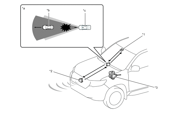
*1 Forward Recognition Camera *2 Millimeter Wave Radar Sensor Assembly *3 Skid Control ECU - - *a Collision Imminent *b Vehicle Ahead *c Own Vehicle - - 
Forward Recognition Camera Detection Area 
Millimeter Wave Radar Sensor Assembly Detection Area -
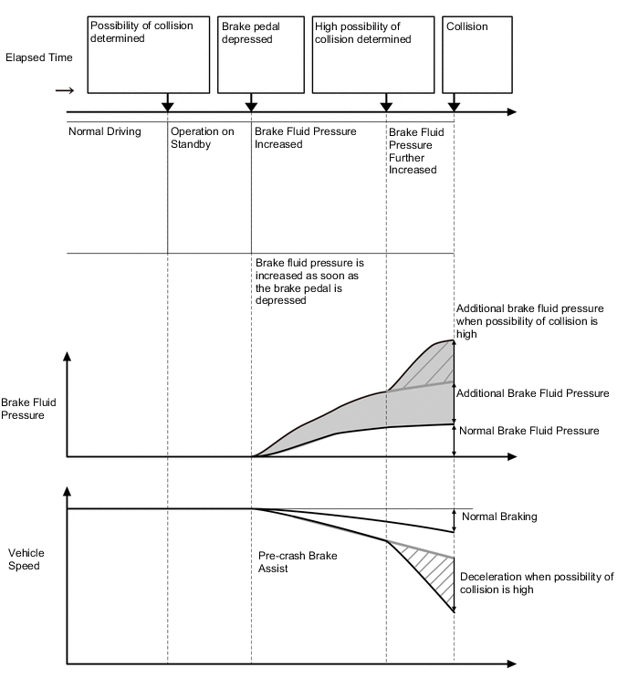
Pre-crash Brake Assist
-
While the pre-crash system has determined that there is a possibility of a collision, brake hydraulic pressure assistance is performed when the driver depresses the brake pedal. Also, the amount of brake hydraulic pressure assistance increases further when the system determines that there is an even higher possibility of a collision.
-
-
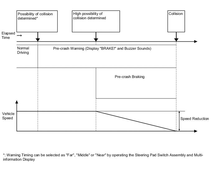
Pre-crash Braking
-
When the pre-crash safety system detects an object such as a vehicle or road structure in front of the vehicle and determines that the possibility of a collision is high, the system displays a warning message on the multi-information display, and sounds the skid control buzzer assembly to warn the driver.
-
When the pre-crash safety system determines that there is a high possibility of a collision, the system performs pre-crash braking control.
-
-
Conditions under which the system may operate even if there is no possibility of a collision
-
In some situations such as the following, the system may determine that is a possibility of a frontal collision and operate.
-
When passing a vehicle or pedestrian
-
When changing lanes while overtaking a vehicle ahead
-
When overtaking a preceding vehicle that is changing lanes
-
When overtaking a preceding vehicle that is making a right/left turn [Case 1]
-
When passing a vehicle in an oncoming lane that is stopped to make a right/left turn [Case 2]
-
When driving on a road where relative location to vehicle ahead in an adjacent lane may change, such as on a winding road [Case 3]
-
When rapidly closing on a vehicle ahead
-
If the front of the vehicle is raised or lowered, such as when the road surface is uneven or undulating
-
When approaching objects on the roadside, such as guardrails, utility pales, trees, or walls
-
When there is a vehicle, pedestrian, or object by the roadside at the entrance of a curve [Case 4]
-
When driving on a narrow path surrounded by a structure, such as in a tunnel or on an iron bridge
-
When there is a metal object (manhole cover, steel plate, etc.), steps, or a protrusion on the road surface or roadside
-
When a crossing pedestrian approaches very close to the vehicle [Case 5]
-
When passing through a place with a low structure above the road (low ceiling, traffic sign, etc.) [Case 6]
-
When passing under an object (billboard, etc.) at the top of an uphill road [Case 7]
-
When rapidly closing on an electric toll gate barrier, parking area barrier, or other barrier that opens and closes
-
When using an automatic car wash
-
When driving through or under objects that may contact the vehicles, such as thick grass, tree branches, or a banner [Case 8]
-
When the vehicle is hit by water, snow, dust, etc. from a vehicle ahead
-
When driving through steam or smoke
-
When there are patterns or paint on the road or a wall that may be mistaken for a vehicle or pedestrian
-
When driving near an object that reflects radio waves, such as a large truck or guardrail
-
When driving near a TV tower, broadcasting station, electric power plant, or other location where strong radio waves or electrical noise may be present
Tech Tips
Depending on the region in which the vehicle was sold, the pedestrian detection function may not be available.
Figure 1. [Case 1]

Figure 2. [Case 2]

Figure 3. [Case 3]

Figure 4. [Case 4]

Figure 5. [Case 5]

Figure 6. [Case 6]

Figure 7. [Case 7]

Figure 8. [Case 8]

-
-
-
-
FUNCTION
-
The pre-crash safety system is equipped with a function that can change the following settings.
-
Pre-crash safety system on (activates) or off (does not activate) setting
-
Warning sensitivity level (Far, Middle or Near) setting
-
Setting Pre-crash Safety System On (Activates) or Off (does Not Activate)
-
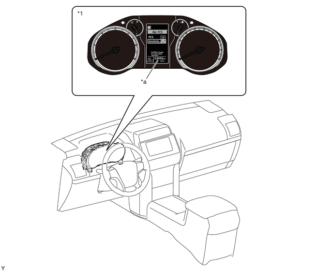
The on (activates) or off (does not activate) setting for the pre-crash safety system can be selected on the multi-information display setting screen.
-
When the pre-crash safety system is set to off, the PCS warning light illuminates. At that time, the multi-information display shows that the pre-crash safety system is off.
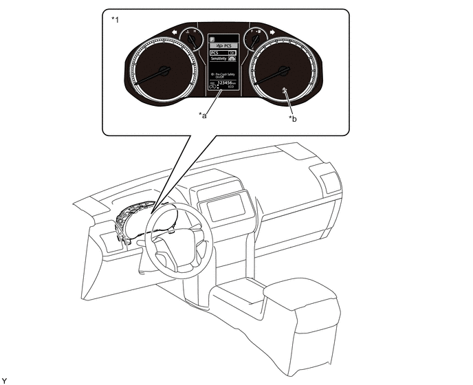
*1 Combination Meter Assembly - - *a Multi-information Display *b PCS Warning Light
Tech Tips
The system is automatically enabled each time the ignition switch is turned on (IG).
-
-
Warning Sensitivity Level Changing
-
The warning sensitivity level of the pre-crash safety system can be switched on the multi-information display setting screen.
*1 Combination Meter Assembly - - *a Multi-information Display - -
Tech Tips
-
The pre-crash safety system is set to Middle by default.
-
When Near is selected, the pre-crash safety system is set to perform a warning operation when there is a short distance between the vehicle and the target object it may collide with (at a timing later than Middle).
-
When Far is selected, the pre-crash safety system is set to perform a warning operation when there is a long distance between the vehicle and the target object it may collide with (at a timing earlier than Middle).
-
The selected warning sensitivity level is maintained even after the engine switch is turned off.
-
-
-
-
DIAGNOSIS
-
Initial Check
-
The driving support ECU assembly performs an initial check on the system for approximately 3 seconds after the ignition switch has been turned on (IG).
-
-
Monitor Function
-
After completing the initial check, the pre-crash safety system becomes ready to operate. During this time, the driving support ECU assembly periodically monitors the system for any malfunctions.
-
-
Diagnostic Trouble Code (DTC)
-
If the driving support ECU assembly detects a malfunction in the pre-crash safety system, it stores a Diagnostic Trouble Code (DTC) in memory.
-
-
-
COMBINATION METER
-
Construction
-
The pre-crash safety system informs the driver of the system operation status by using the PCS warning light, multi-information display, master warning light, meter buzzer and skid control buzzer assembly.
-
-
Operation
-
Pre-crash Safety System Operation Status Display
-
When the driving support ECU assembly, which controls the pre-crash system determines that there is a high possibility of a collision, the driving support ECU assembly sends a display request signal to the combination meter assembly in order to display a warning message on the multi-information display and intermittently sounds the skid control buzzer assembly at the same time, alerting the driver.
Multi-information Display BRAKE ! Skid Control Buzzer Assembly Sounds intermittently
-
-
Indicator Display when Pre-crash Safety System Off
-
When the pre-crash safety system is set to off via the setting screen on the multi-information display, the PCS warning light in the combination meter assembly illuminates and a message is displayed on the multi-information display.
Multi-information Display PRE-CRASH SAFETY
OFF
PCS Warning Light Illuminates -
When the pre-crash brake assist and pre-crash braking cannot be activated due to VSC OFF switch operation, the VSC OFF indicator light and PCS warning light in the combination meter assembly illuminate and a message is displayed on the multi-information display.
Multi-information Display VSC TURNED OFF
PRE-CRASH BRAKE SYSTEM
UNAVAILABLE
PCS Warning Light Illuminates VSC OFF Indicator Light Illuminates
-
-
Pre-crash Safety System Warning Display
-
When the driving support ECU assembly detects a system malfunction or temporary non-activation, the driving support ECU assembly sends a warning display request signal to the combination meter assembly to illuminate or flash the PCS warning light and displays a message on the multi-information display. Also, when the driving support ECU assembly determines that the malfunction occurs due to a failure, the driving support ECU assembly illuminates the master warning light and sounds the meter buzzer.
System Malfunction Predicted Situation System Malfunction Multi-information Display PRE-CRASH SAFETY
MALFUNCTION
VISIT YOUR DEALER
PCS Warning Light Flashes Master Warning Light Illuminates Meter Buzzer Sounds once Millimeter Wave Radar Sensor Assembly Axis Misalignment Predicted Situation Millimeter wave radar sensor assembly axis is misaligned in vertical or horizontal direction Multi-information Display PRE-CRASH SAFETY
UNAVAILABLE
PCS Warning Light Flashes Temperature or Voltage Malfunction of Millimeter Wave Radar Sensor Assembly Predicted Situation Temperature is outside of operation temperature range of millimeter wave radar sensor assembly or battery voltage is lowered Multi-information Display PRE-CRASH SAFETY
UNAVAILABLE
PCS Warning Light Flashes Millimeter Wave Radar Sensor Assembly is Dirty Predicted Situation Dirt is stuck to millimeter wave radar sensor assembly or front grille emblem Multi-information Display PRE-CRASH SAFETY
UNAVAILABLE
CLEAN SENSOR
PCS Warning Light Flashes Forward Recognition Camera Temperature or Voltage Malfunction Predicted Situation Temperature is outside of operation temperature range of forward recognition camera or battery voltage is lowered Multi-information Display FORWARD CAMERA
SYSTEM
UNAVAILABLE
PCS Warning Light Flashes Forward Recognition Camera is Dirty Predicted Situation Dirt, snow, ice, etc. is stuck in windshield glass Multi-information Display FORWARD CAMERA
SYSTEM
UNAVAILABLE
CLEAN WINDSHIELD
PCS Warning Light Illuminates
-
-
-
-
MILLIMETER WAVE RADAR SENSOR
-
The millimeter wave radar sensor assembly consists of a millimeter wave radar circuit, signal processing circuit and CPU.
-
The receiving antennas receive the millimeter wave radar waves that have been reflected.
-
The signal processing circuit detects the distance, the relative speed and the direction of the object by generating millimeter wave radar waves and calculating the signals received by the reception antennas.
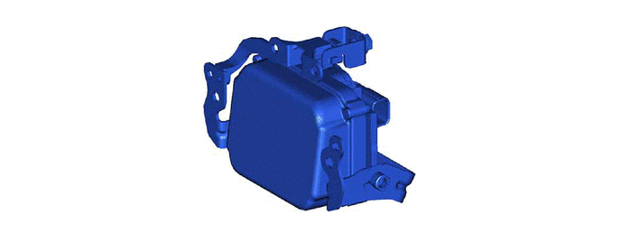
Figure 9. Millimeter Wave Radar Sensor Assembly
-
-
FORWARD RECOGNITION CAMERA
-
The forward recognition camera acquires a video of the area in front of the vehicle and performs image processing to detect objects.
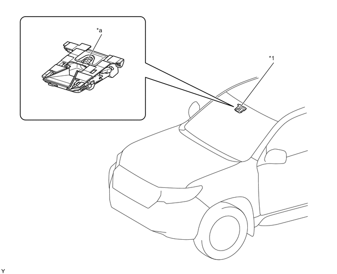
*1 Forward Recognition Camera - - *a Monocular Camera - -
-
-
CAMERA HEATER
-
Construction
-
The camera heater (forward recognition hood with heater sub-assembly) is composed of the sheet heater (heating element) and temperature fuse, etc. Current is run through the sheet heater (heating element) to generate heat and warm the front portion of the forward recognition camera.
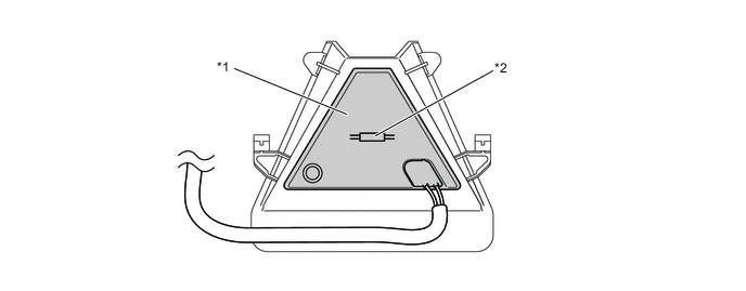
*1 Sheet Heater (Heating Element) *2 Temperature Fuse
-
-
Operation
-
When all of the following conditions have been met, the camera heater (forward recognition hood with heater sub-assembly) operates.
-
The ignition switch is turned on (IG).
-
The ambient temperature is 10°C (50°F) or less.
-
30 seconds or more have elapsed since the camera heater (forward recognition hood with heater sub-assembly) operation stopped.
-
-
After the camera heater (forward recognition hood with heater sub-assembly) operates, the operation will stop when a certain length of time has elapsed.
Tech Tips
Operating time will differ based on vehicle speed, battery voltage and ambient temperature.
-
-