ENTRY AND START SYSTEM
-
FUNCTION OF MAIN COMPONENTS
-
The main components of the entry function have the following functions:
Component Function Electrical Key Transmitter Sub-assembly
-
When receiving the request signals that are output by the indoor electrical key antennas, door electrical key antennas, and outside luggage compartment electrical key antenna, the key outputs information such as the key ID and vehicle ID.
-
When a driver pushes the lock button, unlock button or glass hatch opener button*1 on the key, the key outputs a request signal.
-
Integrates with the mechanical key in order to unlock the doors when the key battery is low.
Certification ECU (Smart Key ECU Assembly)
-
Judges and certifies the key.
-
Controls the indoor electrical key antennas, door electrical key antennas and outside luggage compartment electrical key antenna.
-
Transmits door lock/unlock request signals during the entry function.
-
Receives a glass hatch opener switch operation signal from the main body ECU, checks that the key is in the exterior actuation area around the back door, and sends a glass hatch open signal to the main body ECU when the key identification is confirmed.*1
Main Body ECU (Driver Side Junction Block Assembly)
-
Receives the request signal from the certification ECU and actuates the door lock motors to unlock or lock all the doors, and the back door.
-
Receives a glass hatch opener switch operation signal, and sends it to the certification ECU. When the certification ECU has confirmed the key identification, the main body ECU receives a glass hatch open signal from the certification ECU and drives the glass hatch opener motor.*1
-
Transmits the condition of each door and glass hatch*1 to the certification ECU.
Outside Door Handle Assembly Touch Sensor Transmits the door unlock request signal to the certification ECU. Lock Sensor Transmits the door lock request signal to the certification ECU. Door Electrical Key Antenna Receives the request signal from the certification ECU, and forms an actuation area around the driver's and front passenger's doors. Indoor Electrical Key Antenna Receives the request signal from the certification ECU, and forms an actuation area inside the interior of the vehicle. Outside Luggage Compartment Electrical Key Antenna Receives the request signal from the certification ECU, and forms an actuation area around the luggage compartment. Door Control Receiver Receives the ID code from the key in the actuation area and transmits it to the certification ECU. Back Door Unlock Switch Transmits the door unlock request signal to the certification ECU. Lock Switch Transmits the door lock request signal to the certification ECU. Glass Hatch Opener Switch*1 Transmits the glass hatch opener switch operation signal to the main body ECU. Wireless Door Lock Buzzer
-
Sounds as an answer back for entry lock or unlock to inform the driver.*2
-
Sounds when the warning function is in operation.
Combination Meter Assembly When the certification ECU detects human errors, it warns the driver by illuminating the master warning light and entry warning light, displaying the multi-information display, and sounding the multi buzzer in the combination meter assembly in accordance with the request signal from the ECU. *1: Models with glass hatch opener system
*2: Except models for Europe
-
-
The main components of the start function have the following functions:
Component Function Engine Switch (Push Start Switch)
-
Transponder Key Amplifier
-
Transmits the engine switch signal to the certification ECU.
-
Receives the ID code and transmits it to the certification ECU when the key battery is low.
Electrical Key Transmitter Sub-assembly
-
Receives signals from the antennas and returns the ID code to the door control receiver.
-
When receiving the radio wave that is output by the transponder key amplifier in the engine switch, the key outputs information such as the key ID and vehicle ID.
Indoor Electrical Key Antenna Receives the request signal from the certification ECU, and forms an actuation area inside the interior of the vehicle. Door Control Receiver Receives the ID code from the key and transmits it to the certification ECU. Certification ECU (Smart Key ECU Assembly)
-
Certifies the ID code received from the door control receiver and transmits the certification results to the ID code box and steering lock ECU.
-
Transmits steering lock/unlock request signals.
-
Transmits engine immobiliser set/unset request signals.
-
Records the ID codes between the certification ECU, ID code box, and steering lock ECU.
-
Turns the power source off, on (ACC), on (IG), or START in accordance with the shift lever position*1 and the status of the stop light switch assembly*1, or the state of the clutch start switch assembly*2.
-
Controls the start function in accordance with the signals received from the switches and each ECU.
Stop Light Switch Assembly*1 Outputs the state of the brake pedal to the certification ECU. Clutch Start Switch Assembly*2 Outputs the state of the clutch pedal to the certification ECU. ID Code Box (Immobiliser Code ECU) Receives the steering unlock or engine immobiliser unset request signal from the certification ECU, certifies it, and transmits each unset signal to the steering lock ECU or ECM. ECM
-
Receives the engine start request signal from the certification ECU, turns on the starter relay assembly, and starts the engine.
-
Receives the signal from the ID code box and performs engine ignition*3 and injection.
*1: Models with automatic transmission
*2: Models with manual transmission
*3: Models with gasoline engine
-
-
-
OPERATING CONDITION
-
The special functions of the entry and start system only work when the key is in the actuation area formed by the 6 antennas.
-
The door electrical key antenna and the outside luggage compartment electrical key antenna form the actuation area of the entry function.
-
The No. 1, No. 2 and No. 3 indoor electrical key antenna assemblies form the actuation area of the start function.
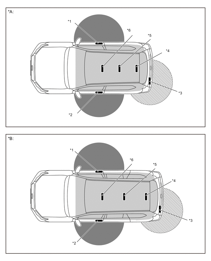
*A 3-door Models *B 5-door Models *1 Door Electrical Key Antenna RH *2 Door Electrical Key Antenna LH *3 Outside Luggage Compartment Electrical Key Antenna *4 No. 3 Indoor Electrical Key Antenna Assembly *5 No. 2 Indoor Electrical Key Antenna Assembly *6 No. 1 Indoor Electrical Key Antenna Assembly 
Exterior Actuation Area 
Interior Actuation Area 
Outside Luggage Compartment Actuation Area - Actuation Area Details Interior The interior actuation area of the indoor electrical key antennas is formed when the driver door is closed when the brake pedal*1 or clutch pedal*2 is depressed, when the engine switch is pressed, when a warning is activated, or when the lock sensor or lock switch is on. Exterior The exterior actuation area formed by the electrical key antennas and outside luggage compartment electrical key antenna is approx. 0.7 m to 1.0 m (27.6 in. to 39.4 in.) from the outside door handle of the front doors, or the outside luggage compartment electrical key antenna. Around Front Door The exterior actuation area of the electrical key antennas is formed by transmitting a request signal every 0.25 seconds while the engine switch is off and each door is locked. In this way, the proximity of a key can be detected. When locking the door using the lock sensor on the outside door handle, the actuation area is formed when the lock sensor is touched. Around Back Door The exterior actuation area of the outside luggage compartment electrical key antenna is formed when the back door lock, unlock or glass hatch opener*3 switch is on. *1: Models with automatic transmission
*2: Models with manual transmission
*3: Models with glass hatch opener system
-
-
FUNCTION
-
Entry Function
-
The entry function consists of the following functions:
Function Outline Entry Illumination When a key enters the exterior actuation area of the door electrical key antenna, each interior light will illuminate. Entry Unlock All doors are unlocked by grabbing the driver or front passenger outside door handle or by pressing the unlock switch of the back door. Entry Lock All doors are locked by touching the lock sensor of the driver or front passenger outside door handle or by pressing the lock switch of the back door. Entry Glass Hatch Opener*1 The glass hatch is opened by pressing the glass hatch opener switch. Warning The entry and start system causes the certification ECU to sound the buzzer in the combination meter assembly and wireless door lock buzzer and uses the multi-information display*2 or key warning indicator*3 in order to alert the driver. Prevention of Key Confinement This function will operate in the following 3 different situations when the key is inside the cabin: when the lock knob is used (keyless lock), when an outside door handle lock sensor or lock switch is used (lock sensor), and when the glass hatch has been closed while all the doors are locked*1. Battery Saving To prevent the key battery and the vehicle battery from becoming discharged, the battery saving function activates when the vehicle remains unused for a long period of time or the key has been detected in the exterior actuation area for more than 10 minutes. Entry Unlock Mode Switching Allows switching between 2 modes that can be operated with the entry unlock function.
-
All Door Mode (Default Setting)
-
Driver Door Mode
Key Cancel The following key functions can be canceled:
-
Entry unlock/lock
-
Back door open
-
Prevention of key confinement
-
Warning
Key Code Registration Function A total of 7 keys can be registered. Key registration enables the registration (writing and storing) of transmitter recognition codes in the EEPROM that is contained in the certification ECU. Wireless Door Lock Control This function is a convenient system for locking and unlocking all the doors at a distance. The operation of this function in the entry and start system is the same as that of the wireless door lock control system. However, the receiver in the certification ECU uses a door control receiver to perform the control. *1: Models with glass hatch opener system
*2: Models with Optitron type combination meter assembly
*3: Models with analog type combination meter assembly
-
-
-
Entry Unlock Function
-
When the key is in any of the exterior actuation areas, all doors are unlocked by grabbing the driver or front passenger outside door handle or by pressing the unlock switch of the back door.*1
-
When the key is in the actuation area surrounding the driver seat, gripping the driver side outside door handle will unlock the driver door only, and gripping the passenger side outside door handle or pressing the back door unlock switch will unlock all doors.*2
-
After all doors have been unlocked, the wireless door lock buzzer sounds twice as an answer back*3 and the hazard lights flash twice at the same time.
Tech Tips
-
*1: All door mode
-
*2: Driver door mode
-
*3: Except models for Europe
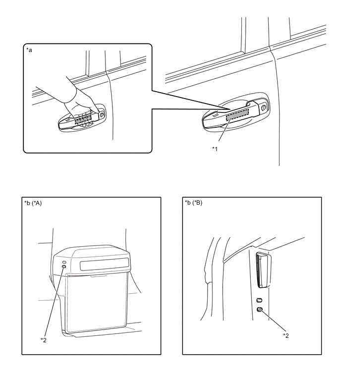
*A Models with Back Door Spare Tire Carrier *B Models without Back Door Spare Tire Carrier *1 Touch Sensor *2 Unlock Switch *a Front Door *b Back Door -
-
-
Entry Lock Function
-
When the key is in any of the exterior actuation areas, all doors are locked while all doors and glass hatch*1 is closed by touching the lock sensor of the driver or front passenger outside door handle or by pressing the lock switch of the back door.
-
After all doors have been locked, the wireless door lock buzzer sounds once as an answer back*2 and the hazard lights flash once at the same time.
-
If the doors do not lock when the lock sensor on the top side of an outside door handle is touched, touch the lock sensors on the top and bottom sides simultaneously by pinching the handle.
-
*1: Models with glass hatch opener system
-
*2: Except models for Europe
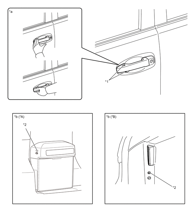
*A Models with Back Door Spare Tire Carrier *B Models without Back Door Spare Tire Carrier *1 Lock Sensor *2 Lock Switch *a Front Door *b Back Door -
-
-
Entry Glass Hatch Opener Function (Models with Glass Hatch Opener System)
-
When the key is in the exterior actuation area around the back door, the glass hatch is opened by pressing the glass hatch opener switch.
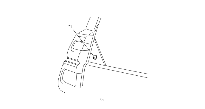
*1 Glass Hatch Opener Switch - - *a Glass Hatch - -
-
-
Start Function
-
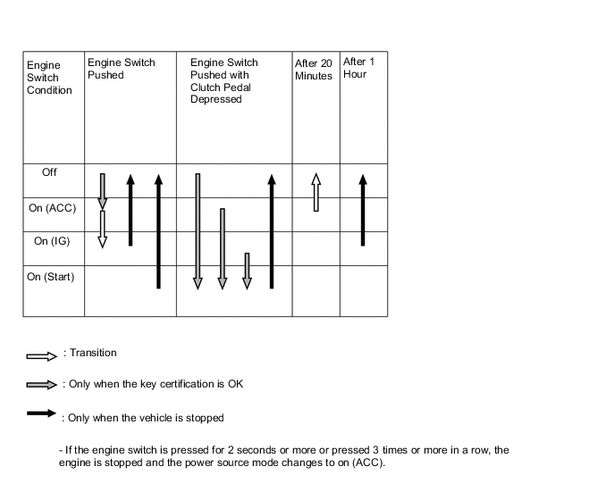
The start function has different power source modes to suit the brake pedal condition and shift lever position*1 or clutch pedal condition*2.
-
When the driver carrying a key enters the vehicle while the power source mode is off and presses the engine switch without depressing the brake pedal*1 or the clutch pedal*2, the power source mode turns on (ACC) to show "POWER ON" on the multi-information display*3 or the key warning indicator will blink green*4. With each pressing of the engine switch, the power source mode switches as follows: off → on (ACC) → on (IG) → off.
-
When the driver who is carrying a key enters the vehicle while the power source mode is off, and depresses the brake pedal while the shift lever is in P or N*1 or depresses the clutch pedal*2, the key warning display*3 illuminates or the key warning indicator*4 illuminates green. Pressing the engine switch with the key warning display*3 or key warning indicator*4 illuminated will cause the engine to start.
-
When starting the engine with the vehicle stopped, pressing the engine switch while the shift lever is in P will cause the power source mode to turn off. Pressing the engine switch when the shift lever is in any position other than P will cause the mode to turn on (ACC).*1
-
When starting the engine with the vehicle stopped, pressing the engine switch will cause the power source mode to turn to off.*2
-
*1: Models with automatic transmission
-
*2: Models with manual transmission
-
*3: Models with Optitron type combination meter assembly
-
*4: Models with analog type combination meter assembly
Figure 1. Transition of Power Source Mode (Models with Automatic Transmission)
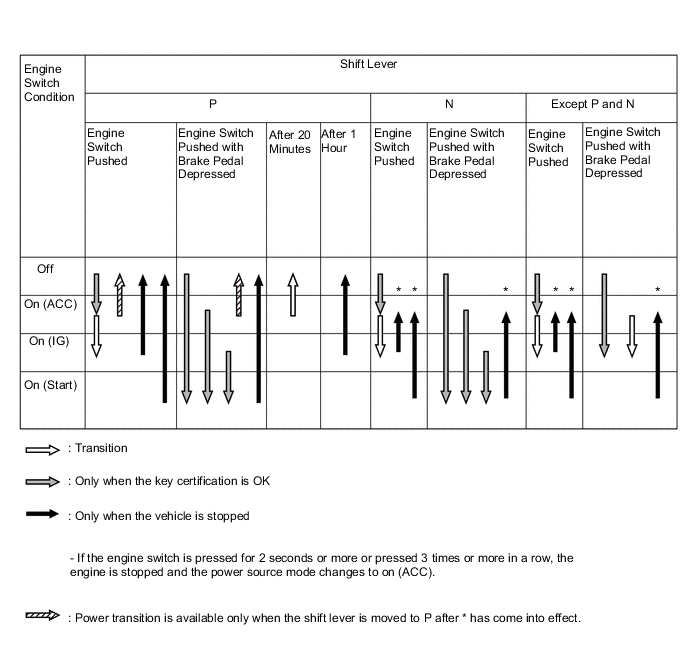
Figure 2. Transition of Power Source Mode (Models with Manual Transmission)
-
-
Transition of the power source mode when the key battery is low or the key is not operating normally due to an electromagnetic interference is as follows:
-
The driver uses the mechanical key (which is built into the key) to unlock the door and enters the vehicle while carrying the key.
-
The driver touches the engine switch with the key while depressing the brake pedal*1 or clutch pedal*2 as follows:
*1: Models with automatic transmission
*2: Models with manual transmission
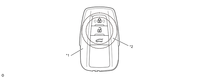
*1 Electrical Key Transmitter Sub-assembly *2 Engine Switch -
Within approximately 10 seconds after the buzzer has sounded, the driver releases the brake pedal*1 or clutch pedal*2 and presses the engine switch.
-
*1: Models with automatic transmission
-
*2: Models with manual transmission
-
With each pressing of the engine switch, the power source mode changes as follows: off → on (ACC) → on (IG) → off.
-
-
Starting the engine when the key battery is low or the key is not operating normally due to an electromagnetic interference is as follows:
-
The driver uses the mechanical key (which is built into the key) to unlock the door, and enters the vehicle while carrying the key.
-
The driver touches the engine switch with the key while depressing the brake pedal with the shift lever in P or N*1.
-
The driver touches the engine switch with the key while depressing the clutch pedal*2.
*1: Models with automatic transmission
*2: Models with manual transmission
*1 Electrical Key Transmitter Sub-assembly *2 Engine Switch -
Within approximately 10 seconds after the buzzer sounds and the key warning display*3 illuminates or key warning indicator*4 illuminates green, the driver presses the engine switch while depressing the brake pedal*1 or clutch pedal*2.
-
*1: Models with automatic transmission
-
*2: Models with manual transmission
-
*3: Models with Optitron type combination meter assembly
-
*4: Models with analog type combination meter assembly
-
Pressing the engine switch starts the engine.
CAUTION:
If you want to stop the engine in an emergency while driving the vehicle, press and hold the engine switch for more than 2 seconds, or press it briefly 3 times or more in succession.
-
If your vehicle has to be stopped in an emergency
-
Steadily step on the brake pedal with both feet and firmly depress it. (Do not pump the brake pedal repeatedly as this will increase the effort required to slow the vehicle.)
-
Shift the shift lever to N.
-
If the shift lever is shifted to N
-
After slowing down, stop the vehicle in a safe place by the road.
-
Stop the engine.
-
If the shift lever cannot be shifted to N
-
Keep depressing the brake pedal with both feet to reduce vehicle speed as much as possible.
-
To stop the engine, press and hold the engine switch for 2 consecutive seconds or more, or press it briefly 3 times or more in succession.
-
Stop the vehicle in a safe place by the road.
Tech Tips
-
If no signals are transmitted to the certification ECU due to a malfunction in the stop light switch assembly*1, park/neutral position switch assembly*1 or clutch start switch*2, the engine will not start even if the driver presses the engine switch while depressing the brake pedal*1 or the clutch pedal*2. In this case, the driver can start the engine by carrying out the following operations. Press the engine switch to turn the power source mode from off to on (ACC), and press the engine switch again and hold it for 15 seconds or more.
-
The above two operations must be carried out only in emergency situations. Under normal conditions, the engine must not be stopped by pressing the engine switch during driving or started without depressing the clutch pedal*2 or brake pedal when the shift lever is in any position other than P or N*1.
-
*1: Models with automatic transmission
-
*2: Models with manual transmission
-
-
-
Memory Call Function
-
The key linked memory call function uses the ID of a key to automatically restore the seat position (using the driving position memory system) and tilt and telescopic position, increasing driver convenience.
Condition Outline Memory Registration When all the following conditions are met, the key ID will be recorded:
-
The engine switch is on (IG).
-
The memory switch (M1 or M2) button is pushed and held.
-
The lock or unlock side of the driver door lock switch is pushed.
Memory Call Operation The memory call function operates when the driver door is opened after the door is unlocked using the entry and start system or wireless door lock control function. Memory Call Cancel When all the following conditions are met, the memory call function can be disabled:
-
The engine switch is on (IG).
-
The driver door is closed.
-
The SET button is pushed and held.
-
The lock or unlock button on the key is pushed and held.
-
-
Memory Registration
Step System Operation (a) Carry the key to be linked to the seat position memory system, close the door and turn the engine switch on (IG). Push the memory switch that is to be linked to the key. (b) While continuing to the memory switch, push the lock or unlock side of the driver door lock switch. (c) During key ID detection, the buzzer in the position control ECU and switch assembly sounds continuously. (d) The main body ECU registers the key ID and each position into memory. (e) When the main body ECU completes recording, it beeps the buzzer in the position control ECU assembly and switch assembly for 0.5 seconds as an answer back. If recording malfunctions, the main body ECU beeps the buzzer in the position control ECU assembly and switch assembly for 3 seconds as an answer back.
-
-
Warning Function
-
When any of the situations below occur, the entry and start system sounds the wireless door lock buzzer, a buzzer in the combination meter assembly, displays a message on the multi-information display*1 and blinks a key warning indicator*2 in order to alert the driver.
-
*1: Models with Optitron display type combination meter assembly
*2: Models with analog display type combination meter assembly
Situation Condition A* The shift lever is in a position other than P and the engine is left running when the driver gets out of the vehicle. B The shift lever is in P* and the engine is left running when the driver gets out of the vehicle. C The engine is left running when a passenger gets out of the vehicle while holding the key. D The key is not within the actuation areas. E The vehicle is driven without a key. F The key is left in the vehicle. G A door is ajar. H The key reminder sounds. I The key battery is weak. J Steering lock does not release. K A malfunction has been detected in a vehicle speed signal, etc. L The engine cannot be started (system/driver error). M Immobiliser system certification confirmation occurs. N Engine start operation guide (ACC) O Engine start operation guide (IG ON) P* The engine switch cannot be turned off (shift lever in any position except P). Q* The engine switch cannot be turned off (shift lever in P). R Auto power off operation occurs. S Engine emergency stop operation is performed. T Engine switch is operated while driving. U Engine switch is operated while driving. V Accessory state W Ignition on state *: Models with automatic transmission
-
Situation A (Models with Automatic Transmission)
-
There are 2 patterns for situation A.
-
Pattern 1:
When the shift lever is in a position other than P, the driver opens the door and attempts to get out of the vehicle. In this situation, the following control is performed:
Possible Effects without Warning Sudden vehicle movement, Vehicle theft, Vehicle roll-away (Vehicle creep, such as when N is selected) Warning Active Condition The warning is activated when all of the following conditions are met:
-
The engine switch is on (ACC) or on (IG).
-
The shift lever is in any position except P.
-
The driver door is opened.
-
The vehicle speed is not detected.
Warning Method Combination Meter Assembly Buzzer Sounds continuously Multi-information Display*1 The following warning message is displayed:
-
SHIFT TO P POSITION WHEN PARKED
Key Warning Indicator*2 - Wireless Door Lock Buzzer - Warning Stop Condition The warning is stopped when one of the following conditions is met:
-
The engine switch is turned off.
-
The shift lever is moved to P.
-
The driver door is closed.
-
The vehicle speed is above 5 km/h (3 mph).
*1: Models with Optitron type combination meter assembly
*2: Models with analog type combination meter assembly
-
-
Pattern 2:
Under the situation of pattern 1, the driver closes the door and attempts to leave the vehicle while holding the key. In this situation, the following control is performed:
Possible Effects without Warning Sudden vehicle movement, Vehicle theft, Vehicle roll-away (Vehicle creep, such as when N is selected) Warning Active Condition The warning is activated when all of the following conditions are met:
-
The engine switch is on (ACC) or on (IG).
-
The shift lever is in any position except P.
-
The driver door is opened → closed.
-
The key is not detected in the vehicle (interior key certification fails).
-
The vehicle speed is not detected.
Warning Method Combination Meter Assembly Buzzer Sounds continuously Multi-information Display*1 The following warning messages are displayed:
-
SHIFT TO P POSITION WHEN PARKED
-
KEY NOT DETECTED CHECK KEY POSITION
Key Warning Indicator*2 Blinks in Yellow Wireless Door Lock Buzzer Sounds continuously Buzzer and Wireless Door Lock Buzzer Warning Stop Condition The warning is stopped when one of the following conditions is met:
-
The engine switch is turned off.
-
The shift lever is moved to P.
-
The vehicle speed is above 5 km/h (3 mph).
-
The key is detected in the vehicle (interior key certification result is OK).
"Shift to P position when parked" Message Warning Stop Condition The warning is stopped when either of the following conditions is met:
-
The shift lever is moved to P.
-
The vehicle speed is above 5 km/h (3 mph).
"KEY NOT DETECTED CHECK KEY POSITION" Message Warning Stop Condition*1 The warning is stopped when either of the following conditions is met:
-
The engine switch is turned off.
-
The key is detected in the vehicle (interior key certification result is OK).
Key Warning Indicator Warning Stop Condition*2 *1: Models with Optitron type combination meter assembly
*2: Models with analog type combination meter assembly
-
-
Situation B
-
There are 3 patterns for situation B.
-
Pattern 1:
When the shift lever is in P*1 and the engine switch is in a mode other than off (the steering remains unlocked), the driver door is opened and the driver attempts to leave the vehicle. In this situation, the following control is performed:
Possible Effects without Warning Vehicle theft Warning Active Condition Condition 1
The warning is activated when both of the following conditions are met:
-
The engine switch is on (ACC).
-
The driver door is open.
Condition 2
The warning is activated when all of the following conditions are met for 1 second:
-
The engine switch is turned off.
-
The steering lock remains unlocked.
-
The driver door is open.
Warning Method Combination Meter Assembly Buzzer Sounds continuously at short and even intervals Multi-information Display*2 - Key Warning Indicator*3 - Wireless Door Lock Buzzer - Warning Stop Condition The warning is stopped when one of the following conditions is met:
-
The engine switch is turned on (IG).
-
The driver door is closed.
-
The engine switch is turned off and the steering wheel lock control is performed.
*1: Models with automatic transmission
*2: Models with Optitron type combination meter assembly
*3: Models with analog type combination meter assembly
-
-
Pattern 2:
Under the situation of pattern 1, the driver opens and closes the driver door and attempts to leave the vehicle while holding the key. In this situation, the following control is performed:
Possible Effects without Warning Vehicle theft Warning Active Condition The warning is activated when all of the following conditions are met:
-
The engine switch is on (ACC) or on (IG).
-
The shift lever is in P.*1
-
The driver door is opened → closed.
-
The key is not detected in the vehicle (interior key certification fails).
-
The vehicle speed is not detected.
Warning Method Combination Meter Assembly Buzzer Sounds once Multi-information Display*2 The following warning message is displayed:
-
KEY NOT DETECTED CHECK KEY POSITION
Key Warning Indicator*3 Blinks in Yellow Wireless Door Lock Buzzer Sounds 3 times Warning Stop Condition The warning is stopped when either of the following conditions is met:
-
The engine switch is turned off.
-
The key is detected in the vehicle (interior key certification result is OK).
*1: Models with automatic transmission
*2: Models with Optitron type combination meter assembly
*3: Models with analog type combination meter assembly
-
-
Pattern 3:
Under the situation of pattern 2, the driver touches the lock sensor on the door outside handle. In this situation, the following control is performed:
Possible Effects without Warning Vehicle theft Warning Active Condition The warning is activated when all of the following conditions are met:
-
The engine switch is on (ACC) or on (IG).
-
The shift lever is in P.*1
-
The key is not detected in the vehicle (interior key certification fails), but detected in an outside detection area (exterior key certification result is OK).
-
The lock sensor on the outside door handle is on (touched) or the unlock switch of the back door is on (pressed).
-
The vehicle speed is not detected.
Warning Method Combination Meter Assembly Buzzer Sounds once Multi-information Display*2 The following warning messages are displayed:
-
KEY NOT DETECTED CHECK KEY POSITION
-
TURN POWER OFF
Key Warning Indicator*3 Blinks in Yellow Wireless Door Lock Buzzer Sounds continuously Wireless Door Lock Buzzer Warning Stop Condition The warning is stopped when one of the following conditions is met:
-
5 seconds elapse.
-
The engine switch is turned off.
-
The shift lever is moved to any position except P.*1
-
The vehicle speed is above 5 km/h (3 mph).
-
The key is detected in the vehicle (interior key certification result is OK).
-
Any door is opened or closed.
"KEY NOT DETECTED CHECK KEY POSITION" Message Warning Stop Condition*2 The warning is stopped when either of the following conditions is met:
-
The engine switch is turned off.
-
The key is detected in the vehicle (interior key certification result is OK).
Key Warning Indicator Warning Stop Condition*3 "TURN POWER OFF" Message Warning Stop Condition The warning is stopped when one of the following conditions is met:
-
60 seconds elapse.
-
The engine switch is turned off.
-
The shift lever is moved to any position except P.*1
-
The vehicle speed is above 5 km/h (3 mph).
*1: Models with automatic transmission
*2: Models with Optitron type combination meter assembly
*3: Models with analog type combination meter assembly
-
-
Situation C
-
When the engine is left running, a passenger leaves the vehicle while holding the key. In this situation, the following control is performed:
Possible Effects without Warning Engine cannot be restarted. Warning Active Condition The warning is activated when all of the following conditions are met:
-
The engine switch is on (ACC) or on (IG).
-
A door other than the driver door is opened → closed.
-
The key is not detected in the vehicle (interior key certification fails).
-
The vehicle speed is not detected.
Warning Method Combination Meter Assembly Buzzer Sounds once Multi-information Display*1 The following warning message is displayed:
-
KEY NOT DETECTED CHECK KEY POSITION
Key Warning Indicator*2 Blinks in Yellow Wireless Door Lock Buzzer Sounds 3 times Warning Stop Condition The warning is stopped when either of the following conditions is met:
-
The engine switch is turned off.
-
The key is detected in the vehicle (interior key certification result is OK).
*1: Models with Optitron type combination meter assembly
*2: Models with analog type combination meter assembly
-
-
Situation D
-
When the key is not in the vehicle, the driver attempts to turn the engine switch on (IG) (emergency key operation* is included). In this situation, the following control is performed:
Tech Tips
*: Emergency key operation is an operation that changes the power source by touching the engine switch with the key.
Possible Effects without Warning User becomes confused Warning Active Condition The warning is activated when all of the following conditions are met:
-
The immobiliser system is set.
-
The key is not in the vehicle (interior key certification fails and transponder certification fails).
-
No records of unlock operation using a mechanical key and key certification failure when the engine switch was turned on (IG).
Warning Method Combination Meter Assembly Buzzer Sounds once Multi-information Display*1 The following warning message is displayed:
-
KEY NOT DETECTED CHECK KEY POSITION
Key Warning Indicator*2 Blinks in Yellow Wireless Door Lock Buzzer - Warning Stop Condition The warning is stopped when one of the following conditions is met:
-
15 seconds elapse.
-
The key is detected in the vehicle (interior key certification result is OK and transponder certification result is OK).
-
30 seconds have elapsed since a door was opened using a door outside door handle.
*1: Models with Optitron type combination meter assembly
*2: Models with analog type combination meter assembly
-
-
Situation E
-
The vehicle starts moving without a registered key in the vehicle. In this situation, the following control is performed:
Possible Effects without Warning Engine cannot be restarted. Warning Active Condition The warning is activated when all of the following conditions are met:
-
The engine switch is on (IG).
-
The warning is activated in situation C.
-
The vehicle speed is above 5 km/h (3 mph).
-
The key is not detected in the vehicle (interior key certification fails).
Warning Method Combination Meter Assembly Buzzer Sounds 9 times Multi-information Display*1 The following warning message is displayed:
-
KEY NOT DETECTED CHECK KEY POSITION
Key Warning Indicator*2 Blinks in Yellow Wireless Door Lock Buzzer - Warning Stop Condition The warning is stopped when either of the following conditions is met:
-
The engine switch is turned off.
-
The key is detected in the vehicle (interior key certification result is OK).
*1: Models with Optitron type combination meter assembly
*2: Models with analog type combination meter assembly
-
-
Situation F
-
The lock sensor on a door outside handle is touched or the lock switch of the back door is pressed to perform entry lock with the key left in the vehicle. In this situation, the following control is performed:
Possible Effects without Warning Vehicle theft Warning Active Condition The warning is activated when all of the following conditions are met:
-
The engine switch is off.
-
All doors and glass hatch*1 are closed.
-
The key is detected in the vehicle (interior key certification result is OK).
-
The lock sensor on the outside door handle is on (touched), the lock button on the key or the back door lock switch is pressed.
-
Any door is unlocked.
-
The vehicle speed is not detected.
Warning Method Combination Meter Assembly Buzzer - Multi-information Display*2 The following warning message is displayed:
-
KEY DETECTED IN VEHICLE
Key Warning Indicator*3 - Wireless Door Lock Buzzer Sounds continuously Wireless Door Lock Buzzer Warning Stop Condition The warning is stopped when any of the following conditions is met:
-
5 seconds elapse.
-
The engine switch is turned on (ACC) or on (IG).
-
The vehicle speed is above 5 km/h (3 mph).
-
Any door is opened.
-
Lock operation is detected.
"Key detected in vehicle" Message Warning Stop Condition The warning is stopped when any of the following conditions is met:
-
60 seconds elapse.
-
The engine switch is turned on (ACC) or on (IG).
-
The vehicle speed is above 5 km/h (3 mph).
-
Lock operation is detected.
*1: Models with glass hatch opener system
*2: Models with Optitron type combination meter assembly
*3: Models with analog type combination meter assembly
-
-
Situation G
-
The lock sensor on the door outside handle is touched or the lock switch of the back door is pressed to perform entry lock, however, a door or glass hatch*1 is ajar. In this situation, the following control is performed:
Possible Effects without Warning Vehicle theft Warning Active Condition The warning is activated when all of the following conditions are met:
-
The engine switch is off.
-
Any door or glass hatch*1 is open other than the door where the entry lock operation is performed.
-
The lock sensor on the outside door handle is on (touched), the lock button on the key or the back door lock switch is pressed.
-
The key is in an outside detection area (exterior key certification result is OK).
Warning Method Combination Meter Assembly Buzzer - Multi-information Display*2 - Key Warning Indicator*3 - Wireless Door Lock Buzzer Sounds continuously Warning Stop Condition The warning is stopped when one of the following conditions is met:
-
5 seconds elapse.
-
The engine switch is turned on (ACC) or on (IG).
-
All doors and glass hatch*1 are closed.
-
Unlock operation is performed using the wireless door lock remote function.
-
Unlock operation is performed using the touch sensor on the inside of an outside door handle or pressing the lock button on the key or the back door lock switch.
*1: Models with glass hatch opener system
*2: Models with Optitron type combination meter assembly
*3: Models with analog type combination meter assembly
-
-
Situation H
-
The door and glass hatch*1 are closed and locked with the key left in the vehicle. In this situation, the following control is performed:
Possible Effects without Warning Vehicle theft Warning Active Condition Condition 1
The warning is activated when all of the following conditions are met:
-
The door is locked using the keyless lock operation.*
-
The key is in the vehicle (interior key certification result is OK).
-
The vehicle speed is not detected.
Condition 2
The warning is activated when all of the following conditions are met (Models compliant with Thatcham only):
-
The engine switch is turned off.
-
All doors and glass hatch*1 are closed and locked.
-
Lock operation without using the entry system is detected.
-
The key is in the vehicle (interior key certification result is OK).
Tech Tips
*: Keyless lock operation is door lock operation without using the key. First, set the lock position (door lock knob) when the door is open, and close the door while pulling the door handle to lock the door.
Warning Method Combination Meter Assembly Buzzer Sounds once Multi-information Display*2 The following warning message is displayed:
-
KEY DETECTED IN VEHICLE
Key Warning Indicator*3 - Wireless Door Lock Buzzer Sounds continuously Wireless Door Lock Buzzer Warning Stop Condition The warning is stopped when one of the following conditions is met:
-
5 seconds elapse.
-
The engine switch is turned to other mode.
-
Any door or glass hatch*1 is opened.
-
Lock operation is detected.
-
The vehicle speed is above 5 km/h (3 mph).
"KEY DETECTED IN VEHICLE" Message Warning Stop Condition The warning is stopped when one of the following conditions is met:
-
60 seconds elapse.
-
The engine switch is turned to another mode.
-
Lock operation is detected.
-
The vehicle speed is above 5 km/h (3 mph).
*1: Models with glass hatch opener system
*2: Models with Optitron type combination meter assembly
*3: Models with analog type combination meter assembly
-
-
Situation I
-
The vehicle is driven using a key that has a low battery. In this situation, the following control is performed:
Possible Effects without Warning Usability function, engine cannot be restarted Warning Active Condition Condition 1
The warning is activated when all of the following conditions are met:
-
The engine switch is turned off after being left on (IG) for more than 20 minutes.
-
The key battery voltage is low (key battery low code is received).
-
The key is in the vehicle (interior key certification result is OK).
-
The vehicle speed is not detected.
Condition 2
The warning is activated when all of the following conditions are met:
-
The engine is stopped → restarted (engine speed is 500 rpm or more).
-
The key battery voltage is low (key battery low code is received).
-
The key is in the vehicle (interior key certification result is OK).
-
The vehicle speed is not detected.
-
The low key battery warning for condition 1 was performed.*
Tech Tips
*: Warning performed after 20 minutes of the engine switch being turned on (IG)
Warning Method Combination Meter Assembly Buzzer Sounds once Multi-information Display*1 The following warning message is displayed:
-
KEY BATTERY LOW HAVE YOUR VEHICLE CHECKED BY A DEALER
Key Warning Indicator*2 Blinks in Yellow Wireless Door Lock Buzzer - Warning Stop Condition The warning is stopped when either of the following conditions is met:
-
15 seconds elapse.
-
The vehicle speed is above 5 km/h (3 mph).
*1: Models with Optitron type combination meter assembly
*2: Models with analog type combination meter assembly
-
-
Situation J
-
The shift lever is moved to a position other than P*1 or the steering lock cannot be released before the steering lock is unlocked. In this situation, the following control is performed:
Possible Effects without Warning Usability function Warning Active Condition The warning is activated when the following condition is met:
The steering lock cannot be released (the steering lock ECU judgment).
Warning Method Combination Meter Assembly Buzzer Sounds once Multi-information Display*2 The following warning message is displayed:
-
PUSH THE ENGINE SWITCH WHILE TURNING THE STEERING WHEEL IN EITHER DIRECTION
Key Warning Indicator*3 Quickly Blinks in Green Wireless Door Lock Buzzer - Warning Stop Condition The engine switch is pushed while the steering wheel is turned left and right.
The warning is stopped when either of the following conditions is met:
-
15 seconds elapse.
-
The steering lock is released.
*1: Models with automatic transmission
*2: Models with Optitron type combination meter assembly
*3: Models with analog type combination meter assembly
-
-
Situation K
-
A vehicle speed signal malfunction or malfunction that interferes with steering lock ECU (steering lock actuator assembly) operation has been detected. In this situation, the following control is performed:
Possible Effects without Warning Malfunction Detection Warning Active Condition The warning is activated when either of the following conditions is met:
-
The steering lock ECU (steering lock actuator assembly) or steering lock/unlock position switch is malfunctioning.
-
The vehicle speed is judged as abnormal or vehicle speed signal communication is malfunctioning.
Warning Method Combination Meter Assembly Buzzer Sounds once Multi-information Display*1 The following warning message is displayed:
-
CHECK ENTRY & START SYSTEM HAVE YOUR VEHICLE CHECKED BY A DEALER
Key Warning Indicator*2 Blinks in Yellow Wireless Door Lock Buzzer - Warning Stop Condition The warning is stopped when either of the following conditions is met:
-
15 seconds elapse.
-
The system returns to normal.
*1: Models with Optitron type combination meter assembly
*2: Models with analog type combination meter assembly
-
-
Situation L
-
When the driver attempts to start the engine after unlocking the driver door using the mechanical key, the key cannot be detected in the vehicle or cannot be detected in the vehicle 2 times in a row. In this situation, the following control is performed:
Possible Effects without Warning Usability function Warning Active Condition The warning is activated when the engine switch is pressed with all of the following conditions met:
-
The immobiliser system is set.
-
The key is not detected in the vehicle (interior key certification fails).
-
The doors were unlocked using a mechanical key or when the engine switch is pressed, a certification error occurs 2 times in a row.
Warning Method Combination Meter Assembly Buzzer Sounds once Multi-information Display*1 The following warning message is displayed for 60 seconds (and then automatically turned off):
-
DEPRESS BRAKE PEDAL, TOUCH ENGINE SWITCH WITH KEY*3
-
DEPRESS CLUTCH PEDAL, TOUCH ENGINE SWITCH WITH KEY*4
Key Warning Indicator*2 Blinks in Yellow Wireless Door Lock Buzzer - Warning Stop Condition The warning is stopped when one of the following conditions is met:
-
60 seconds elapse.
-
The key is detected in the vehicle (interior key certification result is OK and transponder certification result is OK).
-
30 seconds have elapsed since the door was opened using a door outside door handle.
*1: Models with Optitron type combination meter assembly
*2: Models with analog type combination meter assembly
*3: Models with automatic transmission
*4: Models with manual transmission
-
-
Situation M
-
The engine switch is touched with a key when the key battery voltage is low, system operation is canceled or radio interference occurs. In this situation, the following control is performed:
Possible Effects without Warning Usability function Warning Active Condition Transponder certification result is OK. Warning Method Combination Meter Assembly Buzzer Sounds once Multi-information Display*1 The following warning message is displayed:
-
DEPRESS BRAKE PEDAL AND PUSH ENGINE SWITCH TO START*3
-
DEPRESS CLUTCH PEDAL AND PUSH ENGINE SWITCH TO START*4
Key Warning Indicator*2 - Wireless Door Lock Buzzer - Warning Stop Condition The warning is stopped when one of the following conditions is met:
-
10 seconds elapse.
-
The key is detected in the vehicle (interior key certification results is OK).
-
The engine is running at 500 r/min or more.
-
The engine is started.
-
The immobiliser system is set and interior certification is stopped or key certification fails.
*1: Models with Optitron type combination meter assembly
*2: Models with analog type combination meter assembly
*3: Models with automatic transmission
*4: Models with manual transmission
-
-
Situation N
-
The system recognizes the situation that indicates the driver may start the engine (when the driver enters the vehicle or the engine switch is on (ACC)). In this situation, the following control is performed:
Possible Effects without Warning Engine cannot be restarted Warning Active Condition The warning is activated when either of the following conditions is met:
-
When the door is unlocked from the outside of the vehicle with the engine switch off, the driver door is closed → opened.
-
Each time the power source mode is changed from off to on (ACC) without the brake pedal*1 or clutch pedal*2 depressed.
Warning Method Combination Meter Assembly Buzzer - Multi-information Display*3 The following warning message is displayed:
-
DEPRESS BRAKE PEDAL AND PUSH ENGINE SWITCH TO START*1
-
DEPRESS CLUTCH PEDAL AND PUSH ENGINE SWITCH TO START*2
Key Warning Indicator*4 - Wireless Door Lock Buzzer - Warning Stop Condition The warning is stopped when one of the following conditions is met:
-
20 seconds have elapsed since the warning started.
-
The engine is started.
-
Door lock operation is performed from the outside of the vehicle.
-
Wireless operation is performed from the inside of the vehicle or door lock operation is performed using a keyless lock function.
*1: Models with automatic transmission
*2: Models with manual transmission
*3: Models with Optitron type combination meter assembly
*4: Models with analog type combination meter assembly
-
-
Situation O
-
The system recognizes the situation that indicates the driver may start the engine (when the engine switch is on (IG)). In this situation, the following control is performed:
Possible Effects without Warning Engine cannot be restarted Warning Active Condition The warning is activated when either of the following conditions is met:
-
Each time the power source mode is changed from off to on (IG) (the engine is not started) with the shift lever in P and without the brake pedal*1 or clutch pedal*2 depressed.
-
When the engine switch is on (IG) (the engine is not started) with the shift lever in a position other than P, the shift lever is moved to P.*1
Warning Method Combination Meter Assembly Buzzer - Multi-information Display*3 The following warning message is displayed:
-
DEPRESS BRAKE PEDAL AND PUSH ENGINE SWITCH TO START*1
-
DEPRESS CLUTCH PEDAL AND PUSH ENGINE SWITCH TO START*2
Key Warning Indicator*4 - Wireless Door Lock Buzzer - Warning Stop Condition The warning is stopped when one of the following conditions is met:
-
The power source mode is changed to any mode other than on (IG).
-
The vehicle speed is above 5 km/h (3 mph).
-
The shift lever is in a position other than P or N.
*1: Models with automatic transmission
*2: Models with manual transmission
*3: Models with Optitron type combination meter assembly
*4: Models with analog type combination meter assembly
-
-
Situation P (Models with Automatic Transmission)
-
The driver attempts to turn the engine switch off with the shift lever in any position other than P or N. In this situation, the following control is performed:
Possible Effects without Warning Discharged vehicle battery, vehicle roll-away. Warning Active Condition The engine switch is turned off when the shift lever in a position other than P or N. (Excluding an emergency stop by pressing the engine switch 3 times quickly or pressing and holding the engine switch for 2 seconds or more.) Warning Method Combination Meter Assembly Buzzer Sounds once Multi-information Display*1 The following warning message is displayed:
-
SHIFT TO P POSITION WHEN PARKED
Key Warning Indicator*2 - Wireless Door Lock Buzzer - Warning Stop Condition The warning is stopped when either of the following conditions is met:
-
The shift lever is moved to P.
-
The engine switch is turned to a mode other than on (ACC).
*1: Models with Optitron type combination meter assembly
*2: Models with analog type combination meter assembly
-
-
Situation Q (Models with Automatic Transmission)
-
Under situation P, the shift lever is moved to P. In this situation, the following control is performed:
Possible Effects without Warning Discharged vehicle battery, vehicle roll-away (vehicle creep, such as when N is selected) Warning Active Condition The shift lever is moved to P. Warning Method Combination Meter Assembly Buzzer Sounds once Multi-information Display*1 The following warning message is displayed:
-
TURN POWER OFF
Key Warning Indicator*2 - Wireless Door Lock Buzzer - Warning Stop Condition The warning is stopped when either of the following conditions is met:
-
The power source mode is changed to a mode other than on (ACC).
-
The shift lever is in any position other than P.
*1: Models with Optitron type combination meter assembly
*2: Models with analog type combination meter assembly
-
-
Situation R
-
Automatic power off operation occurs. In this situation, the following control is performed:
Possible Effects without Warning Usability function Warning Active Condition The warning is activated when all of the following conditions are met:
-
The shift lever is in P.*1
-
The engine switch is on (ACC) or on (IG).
-
The vehicle speed is not detected and the engine is stopped.
-
The power source is turned off by the automatic power off function (the vehicle remains not operated for 20 minutes with the engine switch on (ACC) or for 1 hour with the engine switch on (IG)).
Warning Method Combination Meter Assembly Buzzer - Multi-information Display*2 The following warning message is displayed:
-
AUTO POWER OFF TO CONSERVE BATTERY
Key Warning Indicator*3 - Wireless Door Lock Buzzer - Warning Stop Condition The warning is stopped when either of the following conditions is met:
-
10 seconds have elapsed since the warning started.
-
The engine switch is turned on (ACC) or on (IG).
*1: Models with automatic transmission
*2: Models with Optitron type combination meter assembly
*3: Models with analog type combination meter assembly
-
-
Situation S
-
The driver stopped the engine using emergency operation while driving. In this situation, the following control is performed:
Possible Effects without Warning Usability function Warning Active Condition The warning is activated when either of the following conditions is met:
-
The engine is stopped by emergency stop operation while driving.
-
After emergency stop operation, the engine switch is turned on (IG), the vehicle speed is detected and the engine is not started.
Warning Method Combination Meter Assembly Buzzer Sounds continuously Multi-information Display*1 The following warning message is displayed:
-
Shift to N and Press Engine Switch to Restart*3
-
Depress clutch and press engine switch to restart*4
Key Warning Indicator*2 - Wireless Door Lock Buzzer - Warning Stop Condition The warning is stopped when one of the following conditions is met:
-
The shift lever is moved to P.*3
-
The vehicle speed is not detected (after the engine switch is turned on (IG) using engine switch operation).
-
The engine switch is operated.
-
The engine has started.
*1: Models with Optitron type combination meter assembly
*2: Models with analog type combination meter assembly
*3: Models with automatic transmission
*4: Models with manual transmission
-
-
Situation T
-
The driver pressed the engine switch while driving. In this situation, the following control is performed:
Possible Effects without Warning Wrong operation is prevented Warning Active Condition The vehicle is moving, the vehicle speed is detected and the engine switch is pressed. Warning Method Combination Meter Assembly Buzzer Sounds intermittently Multi-information Display*1 - Key Warning Indicator*2 - Wireless Door Lock Buzzer - Warning Stop Condition The warning is stopped when either of the following conditions is met:
-
2 seconds have elapsed since the engine switch operation was stopped.
-
The engine switch is turned off.
*1: Models with Optitron type combination meter assembly
*2: Models with analog type combination meter assembly
-
-
Situation U
-
The driver pressed the engine switch while driving. In this situation, the following control is performed:
Possible Effects without Warning Usability function Warning Active Condition The vehicle is moving, the vehicle speed is detected and the engine switch is pressed. Warning Method Combination Meter Assembly Buzzer Sounds once Multi-information Display*1 The following warning message is displayed:
-
Push and Hold Engine Switch for Emergency Stop
Key Warning Indicator*2 - Wireless Door Lock Buzzer - Warning Stop Condition The warning is stopped when either of the following conditions is met:
-
10 seconds elapse.
-
The engine switch is turned off.
*1: Models with Optitron type combination meter assembly
*2: Models with analog type combination meter assembly
-
-
Situation V
-
The power source is changed to on (ACC). In this situation, the following control is performed:
Possible Effects without Warning Usability function Warning Active Condition The power source is changed to on (ACC). Warning Method Combination Meter Assembly Buzzer - Multi-information Display*1 ACCESSORY Key Warning Indicator*2 Slowly Blinks in Green Wireless Door Lock Buzzer - Warning Stop Condition The warning is stopped when the following condition is met:
-
The power source is changed to a mode other than on (ACC).
-
Engine can be started.*2
-
The entry and start system is malfunction.*2
*1: Models with Optitron type combination meter assembly
*2: Models with analog type combination meter assembly
-
-
Situation W
-
The power source is changed to on (IG). In this situation, the following control is performed:
Possible Effects without Warning Usability function Warning Active Condition The power source is changed to on (IG). Warning Method Combination Meter Assembly Buzzer - Multi-information Display*1 IGNITION ON Key Warning Indicator*2 Slowly Blinks in Green Wireless Door Lock Buzzer - Warning Stop Condition The warning is stopped when either of the following conditions is met:
-
The power source is changed to a mode other than on (IG).
-
The display in the odometer area is changed due to user operation.*1
-
Engine can be started.*2
-
The entry and start system is malfunction.*2
*1: Models with Optitron type combination meter assembly
*2: Models with analog type combination meter assembly
-
-
-
-
Battery Saving Function
-
Battery saving preserves the vehicle and key batteries. The battery saving function is activated when the vehicle remains parked for a long time and when the transmitter key is left in the exterior actuation area.
Condition Condition Outline When the vehicle remains parked for a long time. Condition 1:
No response from the key for more than 5 days.
-
Door electrical key antennas and outside electrical key antenna stop emitting signals for creating the actuation area.
When the engine switch is turned on (IG), the control is canceled and the system is returned to normal. Condition 2:
No response from the key for more than 14 days.
-
Door electrical key antennas and outside electrical key antenna stop emitting signals for creating the actuation area.
-
The lock and touch sensors at the front passenger door and the lock and unlock switch at the back door are disabled.
When the engine switch is turned on (IG), the control is canceled and the system is returned to normal. When one of the following conditions is met, the control is returned to condition 1:
-
The doors are locked or unlocked or or glass hatch is opened* using the wireless door lock control function.
-
The doors are locked or unlocked by touching the lock or touch sensor on the driver door.
-
A door is locked or unlocked using the mechanical key.
-
Door is opened → closed.
When the key is left in the exterior actuation area. This state continues longer than 10 minutes.
-
Electrical key antenna that is detecting the key stops emitting signals for creating the actuation area.
The control is stopped when one of the following conditions is met:
-
The doors are locked or unlocked or or glass hatch is opened* using the wireless door lock control function.
-
The doors are locked or unlocked by touching the lock or touch sensor at the driver and front passenger doors, or pressing the lock or unlock switch at the back door.
-
The glass hatch is opened by pressing the glass hatch opener switch.*
-
A door is locked or unlocked using the mechanical key.
*: Models with glass hatch opener system
-
-
In addition to the above functions, the auto power off function helps to reduce drain on the vehicle auxiliary battery by turning the power source mode to off (a) when approximately 20 minutes have elapsed since the shift lever was moved to P* with the power source mode on (ACC) or (b) when approximately 60 minutes have elapsed since the engine was turned off with the shift lever in P, the power source mode on (IG) and the vehicle stationary.
-
*: Models with automatic transmission
-
-
-
Key Battery Saving Function
-
This function cancels the signal reception waiting state of the key, reducing the consumption of current from its battery.
-
The key can be placed into and taken out of battery saving mode. When the key is in battery saving mode, the entry and start system will not be able to detect the key, as the key will not respond to signals from the vehicle. The entry and start system will not operate if the key is in battery saving mode.
-
Pressing the unlock button of the key twice while pressing the lock button (the indicator light of the key blinks 4 times) selects battery saving mode for the key.
-
Battery saving mode can be canceled by pressing any button on the key.
-
-
Entry Unlock Mode Switching
-
The entry unlock mode can be switched between the following 2 modes in accordance with the driver's intention:
-
All Door Mode*1
-
Driver Door Mode
-
-
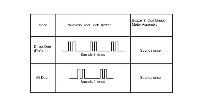
In all door mode, all doors are unlocked by touching the driver or front passenger touch sensor, or by pressing the unlock switch of the back door. In driver door mode, only the driver door is unlocked by touching the driver side touch sensor, and all doors are unlocked by touching the front passenger side touch sensor or by pressing the unlock switch of the back door.
-
The switching of the entry unlock mode is performed when the power source mode is off and the key indicator light is not illuminated. Within a distance range of 1 meter from the vehicle, press and hold both the lock and unlock buttons of the key for approximately 5 seconds.
-
During the switching of the entry unlock mode, the multi buzzer in the wireless door lock buzzer, multi-information display*2, or buzzer in the combination meter assembly will sound to inform the driver of the status of the entry unlock mode. Before switching the entry unlock mode, be sure to turn off the intrusion sensor*3.
Tech Tips
-
*1: Default setting
*3: Models with Optitron type combination meter assembly
*2: Models with intrusion sensor
Figure 3. Models with Optitron Type Combination Meter Assembly
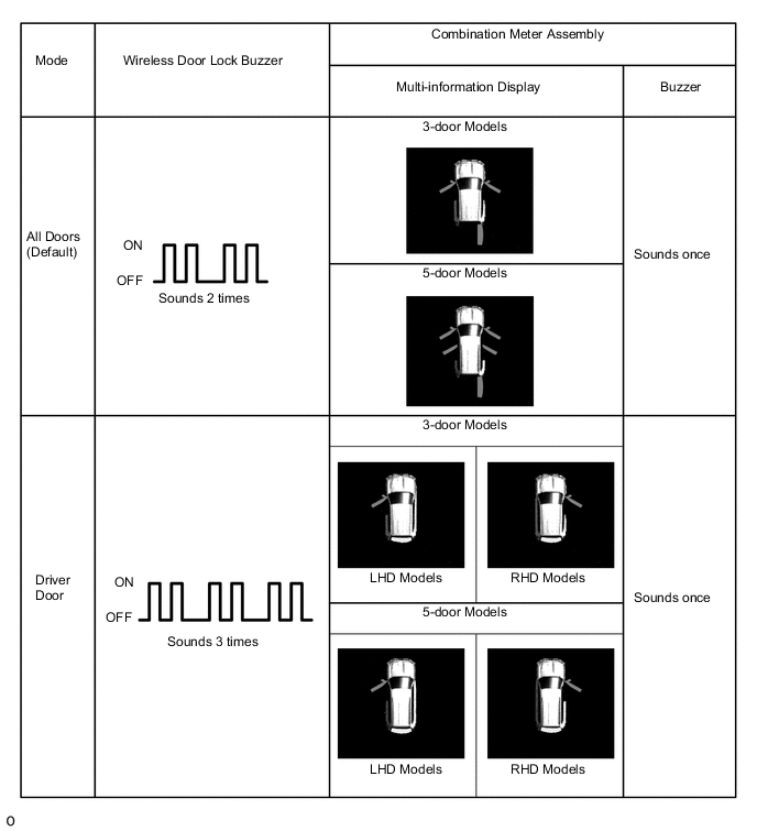
Figure 4. Models with Analog Type Combination Meter Assembly
-
-
-
Key Cancel Function
-
The following system functions can be deactivated by using the key cancel procedure:
-
Entry Lock
-
Entry Unlock
-
Prevention of Key Confinement
-
Warning
-
-
The system functions can be deactivated by using the following key cancel procedure when the engine switch is off and the driver door is closed and unlocked:
Key Cancel Procedure
-
The procedure is as follows:
-
Press the unlock button of the key once.
-
Within 5 seconds of the step above, open the driver door (driver door: close → open).
-
Within 5 seconds of the step above, press the unlock button of the key twice.
-
Repeat close → open for the driver door twice* (driver door: open → close → open → close → open).
-
Press the unlock button of the key twice.*
-
Repeat close → open for the driver door once* (driver door: open → close → open).
-
Within 5 seconds of the step above, close the driver door.
-
When the cancel procedure is complete, the buzzer sounds twice. Meanwhile, when the procedure is performed again to resume the system, the buzzer sounds once.
Tech Tips
*: All these 3 steps are performed within 30 seconds of the previous step.
-
-
-
Key Code Registration Function
-
The table below shows the 4 special ID code registration function modes through which up to 7 different codes can be registered. The codes are electronically registered (written and stored) in the EEPROM. For details, refer to the Repair Manual.
Mode Function Rewrite Clears all previously registered codes and registers only the newly received codes. This mode is used whenever a transmitter or a certification ECU is replaced. Add Adds a newly received code while preserving previously registered codes. This mode is used when adding a new transmitter. If the number of codes exceeds 7, the oldest registered code is cleared first. Confirm Confirms how many codes are currently registered. When adding a new code, this mode is used to check how many codes already exist. Prohibit Clears all registered codes and prohibits the wireless door lock function. This mode is used when a key is lost.
-
-
Wireless Door Lock Control Function
-
The wireless door lock control function has the following functions:
Function Outline All Doors Lock Pressing the lock button of the key locks all doors and back door. All Doors Unlock (1-step Unlock)*1 Pressing the unlock button of the key unlocks all doors and back door. All Doors Unlock (2-step Unlock)*1 Pressing the unlock button on the key once unlocks the driver door, and pressing it again within 3 seconds unlocks all the doors. Glass Hatch Opener*2 Pressing and holding the glass hatch opener button opens the glass hatch. Automatic Lock If none of the doors and glass hatch*2 are opened within 30 seconds after they have been unlocked by the wireless door lock control, all the doors will be locked again automatically. The starting time of the automatic lock function can be changed to 120, 60, or 30 seconds. Answer Back
-
When the doors are being locked or unlocked using the key, the wireless door lock buzzer sounds*3 and the hazard warning lights blink once while locking and twice while unlocking.
-
When the glass hatch is being opened using the key, the wireless door lock buzzer sounds twice as an answer back.*2, *3
Door Ajar Warning If any door or glass hatch*2 is open or ajar, pressing the lock button of the transmitter will cause the wireless door lock buzzer to sound for approx. 5 seconds. Customization The on or off setting of some functions and settings can be performed using the Global Techstream (GTS) or multi-display. In addition, some functions are not available depending on the specification. For details, refer to the Repair Manual. Tech Tips
*1: The function can be set to unlock all the doors after 1 or 2 wireless door lock control operations by using the customization function.
*2: Models with glass hatch opener system
*3: Except models for Europe
-
-
-
-
CONSTRUCTION
-
Electrical Key Transmitter Sub-assembly
-
The key consists of a mechanical key, a transmitter for the wireless door lock control and a transceiver for the entry and start system.
-
The transceiver for the entry and start system receives the signals from the electrical key antenna and returns the ID code to the door control receiver.
-
The transmitter for the wireless door lock control has a lock button and unlock button.
-
When the key battery is low, the radio wave response received from the engine switch is returned to the engine switch by the key.
-
This mechanical key works for the driver's door, but cannot be used to start the engine.
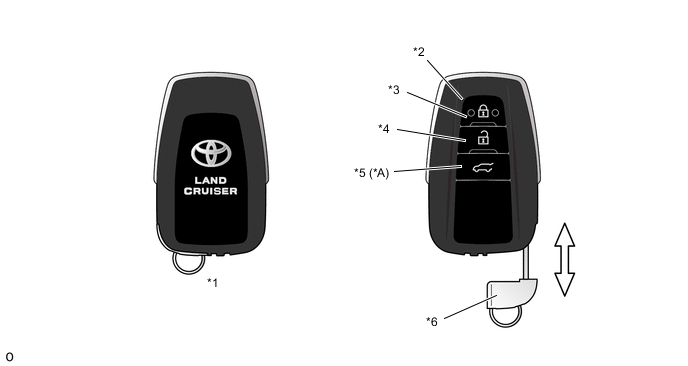
*A Models with Glass Hatch Opener System - - *1 Electrical Key Transmitter Sub-assembly *2 Indicator Light *3 Lock Button *4 Unlock Button *5 Glass Hatch Opener Button *6 Mechanical Key
-
-
Engine Switch (Push Start Switch)
-
The engine switch consists of a momentary type switch, illumination, antenna coil, and transponder key amplifier.

-
-
Certification ECU (Smart Key ECU Assembly)
-
The certification ECU consists of the IG1 and IG2 relay actuation circuits, CPU, and hold circuit.
-
The hold circuit is installed to prevent the power supply to the relays from being cut off when an abnormality occurs in the IG1 and/or IG2 relay actuation circuits during driving.
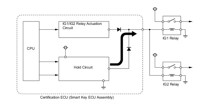
Tech Tips
The certification ECU constantly stores the present power source mode in its memory. Therefore, if the power to the certification ECU is interrupted due to the removal of the battery, the certification ECU restores the power source mode after the battery is reconnected. For this reason, if the battery is removed when the engine switch is in any position other than off, the power will be restored to the vehicle at the same time the power is restored to the certification ECU (by reconnecting the battery). Therefore, before removing or disconnecting the battery, make sure to turn the engine switch off.
-
-
-
DIAGNOSIS
-
The certification ECU can detect malfunctions in the entry and start system when the power source is on (IG).
-
When the ECU detects a malfunction, a message is displayed on the multi-information display*1 orthe key warning indicator blinks in yellow*2 to warn the driver. At the same time, the ECU stores a 5-digit Diagnostic Trouble Code (DTC) in its memory.
-
*1: Models with Optitron type combination meter assembly
*2: Models with analog type combination meter assembly
-
-
The indicator light warning continues for 15 seconds even when the power source mode is turned off.
-
5-digit DTCs can be read after connecting the Global TechStream (GTS) to the DLC3.
-
The entry and start system may not operate successfully if a malfunction occurs.
-
For details, refer to the Repair Manual.
-